
Installation Instructions

Installation Instructions
Document No. 540-568
April 10, 2008
Smoke Control
Listed Unit Conditioner Controller — Electronic
Output
24 V-AC
CH
CH
DO 1 DO 2 DO 3 DO 4 DO 5
NO C NO C NO C NO C NO C
DO 6 DI 3 DI 2 FLN
TRUNK
NO C
POWER
TRUNK
TERMINATIONS
FLN TRUNK
TERMINATIONS
MOUNTING
HOLE
(2)
CONTROLLER
BOARD
COVER
MOUNTING
RAIL
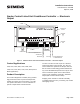
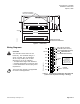
DO LEDS
INPUT/OUTPUT TERMINATIONS
TRANSMIT LED
RECEIVE LED
AI 3
TX RX + - S
+-
S
BST RTS
1 2 3 4 5 6 7 8 9 10 11 12 13 14 15 16
1 2 3 4 5 6 7 8 9 10 11 12 13 14 15 16
TEC0168-SR1
BST LED ROOM TEMPERATURE
SENSOR/MMI PORT
Figure 1. Smoke Control Listed Unit Conditioner Controller — Electronic Output.
Control Applications
2040, 2041, 2050, 2051, 2052, 2053, 2054
2140, 2141, 2150, 2151, 2152, 2153, 2154 (Secure
Mode Applications)
Product Description
The Terminal Equipment Controller (TEC) provides
high performance DDC of pressure-independent,
variable-air-volume zone-level routines. The TEC
can operate stand-alone or can be networked to
perform complex HVAC control functions.
TheTECcanalsobeusedaspartofaSiemens
engineered smoke control system. The TEC are
used to initiate the operations of dampers and fans
but the smoke control strategy will be initiated from
any of the APOGEE field panels and not by the TEC.
These
instructions explain how to field install or
repla
ce a Unit Conditioner Controller—Electronic
Outpu
t (with or without Secure Mode).
Shipping carton includes a controller assembly
(controller board and cover), a mounting rail, and two
self-tapping screws.
I
tem Number: 540-568, Rev. BA
P
age 1 of 8