
Installation Instructions

Document No. 540-568
Installation Instructions
April 10, 2008
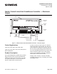
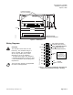
#8 TAPPING SCREW HOLE
11/64 (4) DIA. CLEARANCE
T
EC0169R4
7-5/16 (186)
1-27/32
(47)
3
/16 (5)
C
L
7-11/16 (195)
4-1/8
(105)
DIMENSIONS IN INCHES
MILLIMETERS IN PARENTHESE
S
Figure 5. Dimensions.
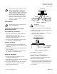
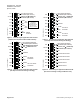
Wiring Diagrams
CAUTION:
The controller’s DOs control 24 Vac
loads only. The maximum rating is 6
VA for each DO. Use an interposing
24 Vac relay module (such as P/N
550-054) for any of the following:
• VA requirements higher than maximum
• Separate transformers to power the load
• Power limited Direct Current (DC) power
requirements
The 24 Vac relay module is not applicable
for smoke control application.
11
1615141312
10
98
1 2 3 4 5 6 7
Y2
Y1
TEC2040-2140WDR1
CCW
CW
COMMON
G
DI 2
DO 6
DO 5
DO 4
DO 3
DO 2
DO 1
AI3 / DI3
NO
C
NO
C
NO
C
NO
C
NO
C
NO
C
+
-
SPARE
DOs
DAMPER
ACTUATOR
WALL SWITCH (OPTIONAL)
OR SPARE DI (DRY CONTACT)
DUCT TEMP SENSOR (OPTIONAL)
100K THERMISTOR ONLY;
OR, SPARE DI (DRY CONTACT)
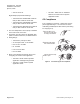
MECHANICAL STOPS
TO PROVIDE
MINIMUM AND
MAXIMUM AIRFLOW
SETTINGS PRO-
VIDED BY OTHERS
Figure 6. Point Wiring for Application 2040 and 2140
(VAV Pressure Dependent Cooling or Heating).
Siemens Building Technologies, Inc. Page 5 of 8