
Installation Instructions

I
II
In
nn
ns
ss
st
tt
ta
aa
all
llll
lla
aa
at
tt
ti
ii
ion
on on
on I
II
In
nn
ns
ss
st
tt
tr
rr
ru
uu
uc
cc
ct
tt
ti
ii
ion
onon
ons
ss
s
Document No. 540-205
Rev. 2, January, 1999
Unit Vent Controller – 0-10 V Output
P
PP
Pa
aa
age
ge ge
ge 1
11
1
o
oo
of
f f
f 19
1919
19
P
PP
Pr
rr
rodu
oduodu
oduc
cc
ct
t t
t D
DD
De
ee
es
ss
sc
cc
cr
rr
ri
ii
ip
pp
pt
tt
ti
ii
ion
onon
on
These instructions explain how to field install (pages 1
through 3) or replace (pages 3 through 4) a Unit Vent
Controller – 0-10V Output (for unit ventilator
applications).
P
PP
Pr
rr
rodu
oduodu
oduc
cc
ct
t t
t N
NN
Nu
uu
um
mm
mbe
bebe
ber
rr
r
540-509
Shipping carton includes a controller assembly
(controller board and cover), a mounting rail, and two
self-tapping/drilling screws.
N
NN
NO
OO
OT
TT
TE
EE
E:
::
: Keep the controller assembly in its static-proof
bag until you install it on the mounting rail.
I
II
In
nn
ns
ss
st
tt
ta
aa
all
llll
lla
aa
at
tt
ti
ii
ion
on on
on C
CC
Con
onon
onv
vv
ven
enen
ent
tt
ti
ii
ion
onon
ons
ss
s
CA
CACA
CAU
UU
UT
TT
TI
II
IO
OO
ON
NN
N:
::
: Equipment damage or loss
of data may occur if the
user does not follow
procedure as specified.
R
RR
Requ
equequ
equi
ii
ir
rr
red
ed ed
ed T
TT
Too
oooo
ools
lsls
ls
• Electro-Static Discharge (ESD) wrist strap
• Small flat-blade screwdriver
• Medium flat-blade screwdriver
• Medium-duty electric drill
• 1/4 in. (6.35 mm) hex nut bit
• Portable Operator’s Terminal with Controller
Interface Software Rev. 2.0 or higher (required
for controller replacement only)
Additional tools needed if not using self-tapping
option:
• 1/4 in. (6.35 mm) hex nut driver
• 1/8 in. (3 mm) bit
P
PP
Pr
rr
re
ee
er
rr
requ
equequ
equisi
isiisi
isit
tt
te
ee
es
ss
s
• Room temperature sensor installed (optional)
• Damper motor installed in the unit ventilator
• A source of 24 Vac Class 2 power available
• Supply power to the unit is OFF
• Duplex receptacle present, or if the fan voltage
exceeds 24 V, an interposing relay is required
for the fan
• If required, controller enclosure installed
E
EE
Ex
xx
xpe
pepe
pec
cc
ct
tt
ted
ed ed
ed I
II
In
nn
ns
ss
st
tt
ta
aa
all
llll
lla
aa
at
tt
ti
ii
ion
on on
on T
TT
Ti
ii
im
mm
me
ee
e
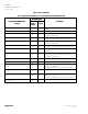
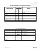
New controller installation 10 Minutes
Replacement (old controller has removable
terminal blocks)
6 Minutes
Replacement (old controller does not have
removable terminal blocks)
16 Minutes
N
NN
NO
OO
OT
TT
TE
EE
E:
::
: You may require additional time for database
work at the field panel.
N
NN
Ne
ee
ew
w w
w I
II
In
nn
ns
ss
st
tt
ta
aa
all
llll
lla
aa
at
tt
ti
ii
ion
on on
on I
II
In
nn
ns
ss
str
trtr
tru
uu
uc
cc
ct
tt
ti
ii
ion
onon
ons
ss
s
N
NN
NO
OO
OT
TT
TE
EE
E:
::
: These steps only refer to new installations.
For replacement instructions, refer to pages 3-4.
The following tasks can be performed by the
electrician:
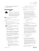
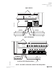
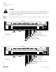
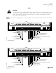
1. Using the mounting rail as a template (Figure 1),
mark the location for the two screw holes where
you will install the controller assembly.
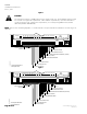
2. Do one
oneone
one of the following:
• I
II
If
f f
f u
uu
us
ss
si
ii
ing
ng ng
ng t
tt
the
he he
he s
ss
se
ee
el
ll
lf
ff
f-
--
-t
tt
ta
aa
app
pppp
ppi
ii
ing
ng ng
ng s
ss
sc
cc
cr
rr
re
ee
ew
ww
ws
ss
s:
::
: Using the
drill and the hex nut bit, fasten the mounting
rail with the screws. (Screws do not require
starter holes.)
• I
II
If
f f
f no
nono
not
tt
t
u
uu
us
ss
si
ii
ing
ng ng
ng t
tt
the
he he
he s
ss
se
ee
el
ll
lf
ff
f-
--
-t
tt
ta
aa
app
pppp
ppi
ii
ing
ng ng
ng s
ss
sc
cc
cr
rr
re
ee
ew
ww
ws
ss
s:
::
: Drill two
1/8 in. (3 mm) pilot holes for the screws. Align
the mounting rail with the holes. Using the
hex nut driver, fasten the mounting rail with
the #6 or #8 screws.
.