
Installation Instructions

540-205
Installations Instructions
Rev. 2, 1/99
P
PP
Pa
aa
age
ge ge
ge 2
22
2
o
oo
of
f f
f 19
1919
19
Siemens Building Technologies, Inc.
Landis Division
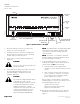
24 V-AC
LAN
TRUNK
COVER
BST
CH
+-
SRXTX RTS
DO 1 DO 2 DO 3 DO 4 DO 5 DO 6
NO C NO C NO C NO C NO C NO C
DO 7
NO C
DO 8
NO C
DI 3 DI 2
AI 3 + -
AO 1DI 4
+ -
AO 2
+ -
AO 3
1 2 3 4 5 6 7 8 9 10 11 12 13 14 15 16 17 18 19 20 21 22 23 24 25 26 27 28
1 2 3 4 5 6 7 8 9 10 11 12 13 14 15 16 17 18 19 20 21 22 23 24 25 26 27 28
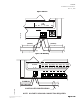
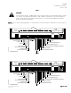
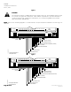
CONTROLLER
BOARD
POWER
TRUNK
TERMINATIONS
TRANSMIT LED
RECEIVE LED
BST LED
LAN
TRUNK
TERMINATIONS
INPUT / OUTPUT TERMINATIONS
DO LEDS
MOUNTING
HOLE
(2)
MOUNTING
RAIL
ROOM TEMPERATURE
SENSOR / MMI PORT
TEC0197R3
CH
+-
S
F
FF
Fi
ii
igu
gugu
gur
rr
re
e e
e 1
11
1.
. .
. U
UU
Un
nn
ni
ii
it
t t
t V
VV
Ven
enen
ent
t t
t C
CC
Con
onon
ontr
trtr
tro
oo
oll
llll
lle
ee
er
r r
r –
– –
– 0
00
0-
--
-10
1010
10V
V V
V O
OO
Ou
uu
ut
tt
tp
pp
pu
uu
ut
tt
t.
..
.
3. Place the ESD wrist strap on your wrist and
attach it to a good earth ground
4. Carefully remove the controller assembly from
the anti-static bag. Center it over the mounting
rail and snap it securely into place.
5. Connect the Local Area Network (LAN) trunk
(Figure 3).
CA
CACA
CAU
UU
UT
TT
TI
II
IO
OO
ON
NN
N:
::
:
Do not connect an earth ground to the
Shield (S) terminal.
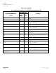
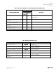
6. Connect the point wiring. Use Tables 1-3 to find
the wiring diagram (Figures 5-23) for your
particular hardware configuration and unit
ventilator application.
CA
CACA
CAU
UU
UT
TT
TI
II
IO
OO
ON
NN
N:
::
:
The Controller’s Digital Outputs (DOs)
control 24 Vac loads only. The
maximum rating is 12 VA for each DO.
For higher VA requirements, 110 or
220 Vac requirements, separate
transformers used to power the load,
or DC power requirements, use an
interposing 220 V 4-relay module
(TEC Relay Module P/N 540-147).
N
NN
NO
OO
OT
TT
TE
EE
E:
::
: Each DO provides a Normally Open (NO)
and a Common (C) terminal. Terminate both
connections of a 24 Vac load directly to the
controller board.
N
NN
NO
OO
OT
TT
TE
EE
E:
::
: The 24 Vac “H” terminal is switched
through a TRIAC to the NO terminations when
the associated DO is energized.
7. To prevent damage to the unit if someone
manually de-energizes the fan at the fan motor
speed switch, do one
oneone
one of the following:
8. Wire the 24 Vac power supply for the
actuators in series with the fan motor speed
switch.
9. Wire a voltage sensing contact to the fan
motor so that if no voltage is sensed, then
the contact will open, cutting the 24 Vac
power supply to the actuators.
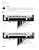
Refer to Figures 21 through 23 as required for
example purposes only. For more detail, refer to
the wiring diagram on the unit.
Figure 21 for Trane units
Figure 22 for Snyder General units
Figure 23 for Nesbitt units
10. Plug the Room Temperature Sensor cable into
the RTS port on the controller board. Refer to
Figure 1.