
Installation Instructions

540-205
Installations Instructions
Rev. 2, 1/99
Siemens Building Technologies, Inc.
P
PP
Pa
aa
age
ge ge
ge 3
33
3
o
oo
of
f f
f 19
1919
19
Landis Division
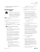
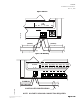
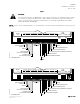
11. Connect the power trunk as shown in Figure 4.
DO NOT apply power to the controller.
The installation is complete.
R
RR
Rep
epep
epl
ll
lac
acac
ace
ee
em
mm
men
enen
ent
t t
t I
II
In
nn
ns
ss
str
trtr
tru
uu
uc
cc
ct
tt
ti
ii
ion
onon
ons
ss
s
CA
CACA
CAU
UU
UT
TT
TI
II
IO
OO
ON
NN
N:
::
:
Replacement of a TEC requires you to
record, re-enter, or update the initial
point values of the controller you are
replacing. These are the points marked
with an asterisk (*) on the Controller
Interface Software (CIS) display.
N
NN
NO
OO
OT
TT
TE
EE
E:
::
: CIS Rev. 2.0 or higher is required for
controller replacement.
The following tasks can be performed by the system
specialist:
1. Place the ESD wrist strap on your wrist and
attach it to a good earth ground.
2. Before disconnecting the old controller, do one
oneone
one
of the following:
N
NN
NO
OO
OT
TT
TE
EE
E:
::
: If the new controller has a newer
firmware revision than the old controller, then
skip to the third bullet.
• If the old controller communicates with the
field panel, then update the controller initial
values at the field panel.
• If the old controller does not communicate
with the field panel, but communicates with
the CIS, or if the controller is stand-alone,
then record the initial values (those marked
with an asterisk (*) on the CIS display).
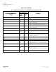
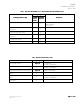
Record these values in Table 4 at the end of
these instructions.
• If the old controller is not communicating at
all, or if the controller you are installing has a
newer firmware revision than the old
controller, then while at the field panel,
follow these steps:
a. Obtain a field panel Point Definition
Report for the LCTLR point. Record the
values in Table 4.
b. View the initial value block. (This
information is valid only since the last
update was made). Record the values in
Table 4.
c. Delete the LCTLR point from the field
panel.
3. Replace the old controller as follows:
The following tasks can be performed by the
electrician:
a. Remove power from the controller.
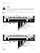
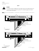
b. If the old controller has the RTS plug
between the LAN trunk and point
terminations, then disconnect the wires
from the power trunk terminal block. If the
old controller has the RTS plug on the
opposite end of the board from the power
trunk terminal block, then remove the power
trunk terminal block.
c. Remove, in order, the controller’s:
• LAN trunk terminal block
• point wiring
• room temperature sensor
d. Remove the old controller assembly from
the mounting rail.
e. Carefully remove the new controller assembly
from the anti-static bag. Center it over the
mounting rail and snap it securely into place.
f. If the old controller has the RTS plug
between the LAN trunk and point
terminations, then remove all terminal
blocks (except the power trunk) from the
new controller. If the old controller has the
RTS plug on the opposite end of the board
from the power trunk terminal block, then
remove all terminal blocks.
g. Plug, in order, the controller’s:
• pre-wired LAN trunk
• point wiring
h. If the old controller has the RTS plug
between the LAN trunk and point
terminations, then rewire power to the
power trunk terminal block. If the old
controller has the RTS plug on the opposite
end of the board from the power trunk
terminal block, then plug the power trunk
terminal block from the old controller into
the new controller.
i. Connect the room temperature sensor.
j. Power up the controller.