
Installation Instructions

540-205
Installations Instructions
Rev. 2, 1/99
P
PP
Pa
aa
age
ge ge
ge 4
44
4
o
oo
of
f f
f 19
1919
19
Siemens Building Technologies, Inc.
Landis Division
The following tasks can be performed by the system
specialist:
4. Set the address and application at the new
controller.
5. Based on what you did in Step 2, do one
oneone
one of the
following:
• If you updated the initial values from the old
controller at the field panel, then when you
set the address and application for the new
controller, the field panel will automatically
send the initial values down to the new
controller. Once this takes place, the
replacement is complete.
• If you manually recorded the initial values in
the table, then enter them into the new
controller. If a field panel is present, then
update the controller’s initial values.
Replacement is complete.
• If there was no communication at the old
controller, or the new controller has a newer
firmware revision than the old controller,
then enter the initial values into the new
controller. At the field panel, add the LCTLR
point and update the controller’s initial
values. The replacement is complete.
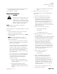
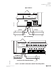
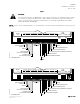
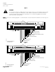
#8 TAPPING SCREW HOLE
11/64 (4) DIA. CLEARANCE
DIMENSIONS IN INCHES
MILLIMETERS IN PARENTHESES
4-1/8
(105)
10-29/32
(277)
3/16
(5)
TEC0198R2
C
L
11-9/32
(287)
1-27/32
(47)
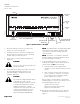
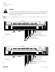
1 2 3 4 5 6 7 8 9 10 11 12 13 14 15 16 17 18 19 20 2122 23 24 25 26 27 28
CH
+-
S