
Installation Instructions

Installation Instructions
Document No. 540-206
July 15, 2009
Dual Duct Cont
roller with One Air Velocity Sensor — Electronic
Output
TEC0200R7
24 V-AC
C
E
H
DO 1 DO 2 DO 3 DO 4 DO 5
NO C NO C NO C NO C NO C
DO 6 DI 3 DI 2
FLN
TRUNK
NO C
POWER
TRUNK
TERMINATIONS
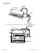
MOUNTING
HOLE
(2)
CONTROLLER
BOARD
COVER
MOUNTING
RAIL
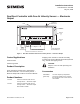
DO LEDS
INPUT/OUTPUT TERMINATIONS
AI 3
TX RX
+-
BST
RTS
1 2 3 4 5 6 7 8 9 10 11 12 13 14 15 16
1 2 3 4 5 6 7 8 9 10 11 12 13 14 15 16
ROOM TEMPERATURE
SENSOR/MMI PORT
FLN TRUNK
+-
S
AVS 1
(optional)
+ - SIG
RECEIVE LED, TRANSMIT LED, AND BST LED
AIR VELOCITY
SENSOR PORTS
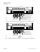
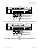
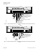
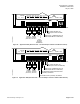
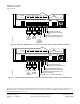
Figure 1. Dual Duct Controller with One Air Velocity Sensor — Electronic Output.
Control Applications
2035 and 2036
2064 through 2066
Product Description
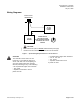
These instructions explain how to field install a
Dual Duct Controller – One Air Velocity Sensor —
Electronic Output with or without an Autozero Module.
Product Numbers
540-106
Dual Duct Controller with One Air
Velocity Sensor — Electronic Output
540-107
Dual D
uct Controller with One Air
Veloc
ity Sensor — Electronic Output
with A
utoZero module.
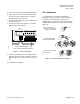
Shipping carton includes a controller assem bly,
mounting rail, Autozero Module with bracket (540-200
only), and two self-tapping screws.
CAUTIO
N:
Keep the unit in its static-proof bag until
installation.
Accessories
540-65
8P25
(pack
of 25)
Low cos
t temporary temp erature
senso
r that enables space control if
the pe
rmanent room or duct sensor is
not in
stalled.
I
tem Number: 540-206, Rev. HA
P
age 1 of 10