
Installation Instructions

Document No. 540-206
Installation Instructions
July 15, 2009
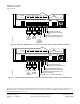
5. Conne ct the point wiring (see Wiring Dia g ra ms).
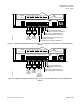
6. 540-200 only: Install the Autozero Module and
connect the wires to DO6 (Figure 5). Refer to
installation instruction 540-199.
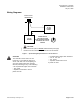
7. Plug the room temperature sensor cable into the
RTS port (Figure 1).
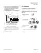
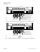
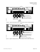
8. Connect the power trunk (Figure 3). DO NOT
apply power to the controller.
24 V-AC
CEH
DO 1 DO 2 DO 3 DO 4 DO 5
NO C NO C NO C NO C NO C
NO
1 2 3 4 5 6 7 8 9 10 11 1
2
1 2 3 4 5 6 7 8 9 10 11 1
COMMON
24 VAC HOT
CONTROLLER POWER WIRING
NOTE: NO EARTH GROUND CONNECTION
TEC0253R2
Figure 3. Power Trunk Wiring.
9. Conne ct the tubing from the air velocity sensor
pickups to the ports on the controller or Autozero
Module (Figure 5). Connect HI to HI and LO to
LO.
The installation is complete.
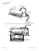
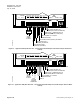
CE Compliance
If CE compliance is required, the Equipment
Controller must be mounted in a grounded metal
enclosure and a ferrite filter must be placed
approximately 1 cm from the end of the cable being
shielded (RTS cable[ and the point wiring for AI3])
(Figure 4).
TEC0320R3
1- 2 cm
1
Place the filter 1-2 cm
from the end of the cable
or wiring to be shielded.
2
Wind the cable tightly
twice around the filter.
3
Close the filter and wrap
with a zip tie.
Figure 4. Ferrite filter(s) for CE Compliance.
Siemens Building Technologies, Inc. Page 3 of 10