
Installation Instructions

Document No. 540-206
Installation Instructions
July 15, 2009
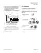
Wiring Diagrams
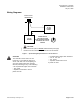
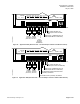
24 VDC
POWER
SUPPLY
4-20 mA
SENSOR
ENTIRE CIRCUIT
MUST BE ISOLATED
WITH NO EARTH GROUND,
INCLUDING THE 4-20 mA
SENSOR
DO NOT use the same transformer to power both the sensor and controller.
Each 4-20mA sensor requires a SEPARATE, dedicated 24 VDC power supply.
-+
-
+
TEC0429R2
ANALOG INPUT
TERMINATIONS
CAUTION:
Figure 7. Special Wiring Requirements for 4–20 mA Sensors.
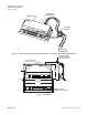
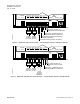
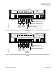
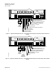
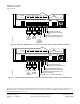
CAUTION:
The controller ’s D Os control 24 Vac
loads only. The maximum rating is 12
VA for each DO. Use an interposing 24
Vac relay module ([550-054, 550-048,
550-050, 550-052]) for any of the following:
• VA requirements higher than maximum
• DC pow er
• Separate transformers used to
power the load
— VA requirements higher than maximum
— 110 or 220 Vac
— DC power
— Separate transformers used
to power the load
Siemens Building Technologies, Inc. Page 5 of 10