
Installation Instructions

Installation Instructions
Document No. 540-208
July 15, 2009
Dual Duct Cont
roller with Two Air Velocity Sensors – Electronic
Output
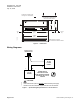
24 V-AC
FLN
TRUNK
COVER
BST
CH
+-
SRXTX RTS
DO 1 DO 2 DO 3 DO 4 DO 5 DO 6
NO C NO C NO C NO C NO C NO C
DO 7
NO C
DO 8
NO C
DI 3 DI 2
AI 3
1 2 3 4 5 6 7 8 9 10 11 12 13 14 15 16 17 18 19 20
1 2 3 4 5 6 7 8 9 10 11 12 13 14 15 16 17 18 19 20
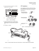
AIR VELOCITY
SENSOR PORTS
HI
LO
CONTROLLER
BOARD
POWER
TRUNK
TERMINATIONS
TRANSMIT LED
RECEIVE LED
BST LED
FLN
TRUNK
TERMINATIONS
INPUT / OUTPUT TERMINATIONS
DO LEDS
MOUNTING
HOLE
(2)
MOUNTING
RAIL
ROOM TEMPERATURE
SENSOR / MMI PORT
TEC0044R5
LO
HI
CH
+-
S
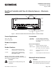
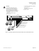
Figure 1. Dual Duct Controller with Two Air Velocity Se
nsors – Electronic Output.
Control Applications
2237 and 2238
2267 through 2269
Product Description
TBD
Product Numbers
540-506
Dual Duct Controller with Two Air
Velocity Sensors – Electronic Output
540-507
Dual Duct Controller with Two Air
Velocity Sensors – Electronic Output
with AutoZero module.
Shipping carton includes a controller assembly,
mounting rail, Autozero Module with bracket (540-200
only), and two self-tapping screws.
CAUTION:
Keep the unit in its static-proof bag until
installation.
Accessories
540-658P25
(pack of 25)
Low cost temporary temperature
sensor that enables space control if
the permanent room or duct sensor is
not installed.
Parts for CE Compliance:
550-705
Clamp-on ferrite filter 10 pack
588-100 series
Approved 2-RJ11 RTS cable in 25’,
50’, or 100’ (7.6-m, 15.2-m, 30.48-m).
540-155
Metal Small Equipment Controller
Enclosure
550-002
Large Equipment Controller Enclosure
Warning/Caution Notations
WARNING:
Personal injury/loss of life may occur if you
do not follow the procedures as specified.
I
tem Number: 540-208, Rev. EA
P
age 1 of 8