
Installation Instructions

Document No. 540-208
Installation Instructions
July 15, 2009
CAUTION:
Equipment damage or loss of data may
occur if you do not follow the procedures
as specified.
Expected Installation Times
10 minutes.
Required Tools and Materials
• Flat-blade screwdriver (1/8-inch blade width).
•Smallflat-blade screwdriver
• Cabling and connectors. See the section.
• Cordless drill/driver set
Prerequisites
• Wiring conforms to NEC and local codes and
regulations. For further information refer to the
Wiring Guidelines manual (125-3002).
• 24 Vac Class II power source available.
• Supply power to the controller is OFF.
• Any application specific hardware or devices
installed.
• Room temperature sensor installed (optional).
(If desired, a low-cost temporary temperature
sensor is available that plugs into the RTS
port of the TEC (P/N 540-658P25), providing
temperature input and actual space control
until the permanent room or duct sensor is
installed.)
If the controller is being installed on a box
with 1 or more stages of electric heat,
the 550-809 MOV with pre-terminated
spade connectors must be installed across
the manufacturer-supplied airflow switch.
MOVscanbeinstalledatthetimethe
controller is factory mounted; coordinate
with the box manufacturer prior to order
placement. For field installation, see Metal
Oxide Varistor Kit Installation Instructions
(540-986).
Instructions
NOTE: All wiring must conform to NEC and
local codes and regulations.
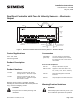
1. Secure the mounting rail (Figure 1) in the
controller’s desired location.
2. Place the ESD wrist strap on your wrist and attach
it to a good earth ground.
3. Remove the controller from the static proof bag
and snap it into place on the mounting rail.
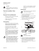
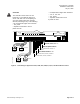
4. Connect the FLN (Figure 2).
FLN
TRUNK
TX RX
+-
S BST RTS
(SHIELD) (SHIELD)
(+)
(+)
(-)
(-)
TEC0042R4
Figure 2. FLN Wiring.
CAUTION:
Do not ground the shield.
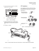
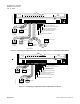
5. Connect the point wiring (see Wiring Diagrams).
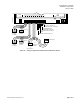
6. 540-507 only: Install the Autozero Module and
connect the wires to DO7 and DO8 (Figure 5).
Refer to installation instruction 540-199.
7. Plug the room temperature sensor cable into the
RTS port (Figure 1).
Page 2 of 8 Siemens Building Technologies, Inc.