
Installation Instructions

Document No. 540-208
Installation Instructions
July 15, 2009
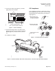
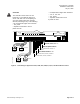
8. Connect the power trunk (Figure 3). DO NOT
apply power to the controller.
24 V-AC
CEH
DO 1 DO 2 DO 3 DO 4 DO 5
NO C NO C NO C NO C NO C
NO
1 2 3 4 5 6 7 8 9 10 11 1
2
1 2 3 4 5 6 7 8 9 10 11 1
COMMON
24 VAC HOT
CONTROLLER POWER WIRING
NOTE: NO EARTH GROUND CONNECTION
TEC0253R2
Figure 3. Power Trunk Wiring.
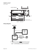
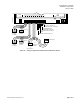
9. Connect the tubing from the air velocity sensor
pickups to the ports on the controller or Autozero
Module (Figure 5). Connect HI to HI and LO to
LO.
The installation is complete.
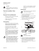
CE Compliance
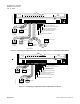
If CE compliance is required, a ferrite filter must be
placed approximately 1 cm from the end of the cable
being shielded (RTS cable[ and the point wiring for
AI3]) (Figure 4).
TEC0320R3
1- 2 cm
1
Place the filter 1-2 cm
from the end of the cable
or wiring to be shielded.
2
Wind the cable tightly
twice around the filter.
3
Close the filter and wrap
with a zip tie.
Figure 4. Ferrite filter(s) for CE Compliance.
24 V-AC
LAN
TRUNK
BST
C
H
+
-
S
RX
TX
RTS
DO 1
DO 2
DO 3
DO 4
DO 5
DO 6
NO C NO C NO C
NO C NO C
NO C
DO 7
NO C
DO 8
NO C
DI 3
DI 2
AI 3
1 2 3 4 5 6 7 8 9 10 11 12 13 14 15 16 17 18 19 20
1 2 3 4 5 6 7 8 9 10 11 12 13 14 15 16 17 18 19 20
AIR VELOCITY
SENSOR PORTS
TEC0045R4
HI
HI
LO
LO
C H
+ - S
CONTROLLER
AIR VELOCITY
SENSOR PORTS
IN COLD DUCT
AUTOZERO
MODULE 1
LO
HI
AIR VELOCITY
SENSOR PORTS
IN HOT DUCT
AUTOZERO
MODULE 2
LO
HI
Figure 5. Dual Duct Controller with Two Air Velocity Sensors – Electronic Output with Autozero Module.
Siemens Building Technologies, Inc. Page 3 of 8