
Installation Instructions

Document No. 540-208
Installation Instructions
July 15, 2009
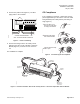
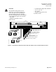
#8 TAPPING SCREW HOLE
11/64 (4) DIA. CLEARANCE
2-1/2 (64) CLEARANCE REQUIRED
FOR PROPER INSERTION OF
POLYETHYLENE TUBING
DIMENSIONS IN INCHES
MILLIMETERS IN PARENTHESES
4-1/8
(105)
10-29/32
(277)
3/16
(5)
TEC0050R4
C
L
11-9/32
(287)
1-27/32
(47)
1 2 3 4 5 6 7 8 9 10 11 12 13 14 15 16 17 18 19 20
CH
+-
S
Figure 6. Dimensions.
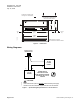
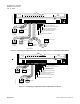
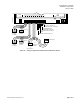
Wiring Diagrams
24 VDC
POWER
SUPPLY
4-20 mA
SENSOR
ENTIRE CIRCUIT
MUST BE ISOLATED
WITH NO EARTH GROUND,
INCLUDING THE 4-20 mA
SENSOR
DO NOT use the same transformer to power both the sensor and controller.
Each 4-20mA sensor requires a SEPARATE, dedicated 24 VDC power supply.
-+
-
+
TEC0429R2
ANALOG INPUT
TERMINATIONS
CAUTION:
Figure 7. Special Wiring Requirements for 4–20 mA Sensors.
Page 4 of 8
Siemens Building Technologies, Inc.