
Installation Instructions

Document No. 129-145
Installation Instructions
November 18, 2013
• Power leads, analog output, door status,
and annunciator wiring should be 14 to
22 AWG stranded wire.
• BACnet suggested wiring is 22 AWG
stranded wire in a shielded cable, a +,-, Gnd
(S) and shield should be run. This can be
two twisted pairs with a separate cable
shield. One twisted pair is used for
communications, the second twisted pair
can be used for communications ground and
the shield wire can be connected to the
other device shield wires.
Plumbing (Attaching Pressure
Tubing)
CAUTION:
Always attach tubing to the RPM header
and then place Header onto RPM. This will
prevent overpressure from crimped or
collapsed tubes.
Use the following procedure for all room types:
positive, negative or neutral:
Typically a Pressure Tap Plate is installed in the
monitored room. Often, stiff nylon 1/4-inch tubing is
used for running pressure signals from the RPM to
the monitored spaces. To prevent buckling and
collapse of this stiff tubing inside the electrical box,
use the supplied strain relief tubing assemblies (2) to
transition from the field tubing to the pressure fittings
on the RPM. The strain relief tubing assemblies are
an integrated system of tubing (2-1/4-inch long),
tubing nipple and over-molded spring to prevent
crimping or buckling of the tubing in the field.
Attach pressure tubing as follows:
1. Connect the 1/4-inch O. D. tubing running from
the Tap Plate (or other pressure connection
from the monitored space) to the 4-1/2 × 4-1/2-
inch electrical box for the RPM.
2. Install the barbed side of one of the strain relief
tubing assemblies onto the end of the field-
installed tubing.
3. Thread the tubes through the conduit opening
at the bottom of the electrical box.
4. Push the open end of the strain relief tubing
assembly onto the RPM pressure tube header
(H1) port labeled “+”.
NOTE: The header is an Electro-Pneumatic
(EP) assembly. “+” indicates
(Positive) pressure, and “-” indicates
negative or reference pressure.
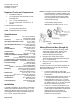
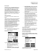
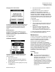
SEN0559R1
Pressure Tap
Plate Tubing
Electrical Box
RPM Header H1
Silicone Tubing
Figure 2. Plumbing Inside Electrical Box.
5. For the most pressure stable operation, a Tap
Plate installed in the reference pressure area is
also recommended. In this case, install the Tap
Plate in a hallway or reference space:
a. Attach the tube to the RPM in the same way
as for the + port, except attach the tube to
the “-” port on the pressure tube header.
b. Tighten swivel fittings on the RPM Header
H1 assembly if they become loose, 9 in lb.
max.
c. Verify that the tubes are not buckled, which
could close off pressure signal at end of
installation.
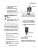
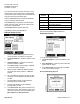
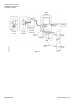
SEN0560R1
1/4” O.D. Tubing
Figure 3. Pressure Tap Plate.
Wiring, Finish
Alarm Relay Output
The Single Pole Single Throw (SPST) relay output
can be used for remote signaling of alarm condition.
A form “C” contact rated at 1A is available. Connect
to J4, P1 and P4. This relay can be used as a dry
contact for remote indication.
Item Number 129-145, Rev. EA Page 3 of 11