
Installation Instructions

Document No. 129-145
Installation Instructions
November 18, 2013
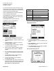
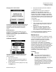
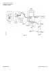
Optional Remote Annunciator Wiring
Non-Siemens Remote Annunciator
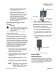
The RPM can drive annunciators that are powered
by a 15V supply, 50 mA max current draw, and
accept a 15V trigger. In Figure 4, the Remote
Annunciator connector is at left, and the RPM
connector is at right:
1. On J4 of the RPM, jumper P1 to P2, this will
connect the internal 15V supply to the common
of the internal alarm relay.
2. Connect P2 to A1 (Located on Remote
Annunciator), this supplies 15V excitation to the
Annunciator for powering the circuit during
normal conditions.
3. Connect P3 of J4 to A2 of Remote Annunciator
J1. This is the 15V power return.
4. Connect P4 of RPM J4 to A3 terminal of
Remote Annunciator J1. This is the alarm
trigger.
When an alarm occurs and after the programmed
alarm delay times out the internal relay will supply
15V to the Annunciator circuit to actuate the audible
beeper and the red LED.
SEN0561R2
J1:Annunciator
J4:RPM
+15 VDC Excitation A1
+15 VDC Trigger A3
Ground A2
Jumper
P4 (Annunciator Trigger)
P3 (Ground)
P2 (+15 VDC Excitation)
P1 (Relay N.O.)
Figure 4. Remote Annunciator Wiring.
Door Status Switch Wiring
1. Install the door switch into the door jamb.
2. Wire to the normally open (N.O.) side of the
door jamb contact switch. The RPM will indicate
the status of door position. A contact closure
indicates that the door is closed. This is a low
voltage circuit (5 Vdc).
Page 4 of 11 Siemens Industry, Inc.
3. Run two wires from the door switch to
connector J6 on the RPM (See
Figure 7). The
door input status function is enabled in the
SETUP ALARMS menu screen.
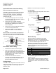
Analog Output
The RPM can be configured to have either current (4
to 20 mA) or voltage (0 to 5 or 0 to 10 Vdc) outputs.
Voltage output—pin 1; Current output—pin 2;
Common—pin 3.
NOTE: No external excitation is required.
Current Output
The RPM supplies its own loop power; do not wire in
a separate power supply.
SEN0563R1
Current Output
1 V Out 0 to 5, 0 to 10 VDC
2 C Out 4 to 20 mA
3 Common
+
-
Receiver
(mA)
Figure 5.
Voltage Output
SEN0564R1
Voltage Output
1 V Out 0 to 5, 0 to 10 VDC
2 C Out 4 to 20 mA
3 Common
+
-
Receiver
(V)
Figure 6.
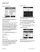
BACnet Set-up
BACnet hardware is implemented as isolated
RS485. Wire to Connector J2, labeled RS-485.
Connect tx line to +(A), rx to –(B) and ground wires
to S. Connect Shields together with wire nut.
Hardware configuration is done using a 5-position
DIP switch (S1) located in the upper right hand
section of the PCBA as well as through the touch
screen interface.
Position Function
1 MAC address enabled
2 N/C Not Connected
3 Pull up resistor
4 Termination resistor
5 Pull down resistor
Use a small, flat-blade screwdriver or pen to push
the switch to the right to turn that function on;
otherwise, it is off.
There is a BACnet setup screen that is enabled by
pushing position 1 switch to the ON position. After
configuration the switch must be moved to the OFF
position.