
Installation Instructions

Installation Instructions
Document No. 545-429
Rev. 4, September, 2002
FLN Controller Board
Item Number 545-429-04 Page 1 of 3
Product Description
The Floor Level Network (FLN) Controller Board
controls floor level network devices such as,
Terminal Equipment Controllers (TECs), Differential
Pressure Monitors (DPMs), and Unitary Controllers
(UCs).
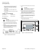
The controller board mounts in an enclosure and can
operate independently with associated FLN devices
or as part of the building level network (BLN). Once
installed, the controller board is positioned
approximately 2-1/4-inches off the back wall of the
enclosure on a board bracket and four standoffs.
The controller board has two man-machine interface
(MMI) ports—the MMI and the MMI MODEM—which
are RS-232 ports with quick-connect RJ-11 jacks.
NOTE: All circuits are supervised, except for the
MMI MODEM and MMI ports.
Power is supplied to the controller board via a
12 Vdc plug-in power supply. For 115 Vac setups,
use part number 545-132. For 230 Vac setups, use
part number 545-136.
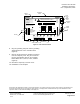
The memory board, located beneath the memory
board cover and plugged into the controller board,
contains the firmware that controls the FLN
Controller. The memory board’s flash read-only
memory (ROM) stores the microprocessor
instruction code, PPCL compiler, and the operator
interface.
The following documents provide further information
about the system installation and programming
constraints:
• FLN Controller 115 Vac/230 Vac Plug-in
Power Supplies Installation Instructions
(545-431)
• Smoke Control Application and Engineering
Manual (125-1806)
• APOGEE Automation Technical Reference on
InfoLink.
Product Numbers
545-796 APOGEE FLN Controller 8 MB (4 MB flash,
4 MB RAM) with Firmware 2.x
545-794 APOGEE FLN Controller 6 MB (4 MB flash,
2 MB RAM) with Firmware 2.x
545-489 APOGEE FLN Controller 4 MB (2 MB RAM)
(repaired only)
545-442 APOGEE FLN Controller 3 MB (1 MB RAM)
(repaired only)
545-793 FLN Controller 3 MB (1 MB RAM)—English
Caution Notations
CAUTION:
Equipment damage or loss
of data may occur if you do
not follow a procedure as
specified.
Required Tools and Materials
Electro-static discharge (ESD) wrist strap
Expected Installation Time
3 minutes
Prerequisites
CAUTION:
The controller board must only be mounted
in an FLN Controller enclosure or LAN
Controller enclosure upgrade.
• FLN Controller enclosure, 115 Vac (545-791)
or 230 Vac (545-792), mounted on wall or
existing LAN Controller enclosure with an FLN
controller board bracket assembly (545-135).
• All conduit runs to enclosure complete.
• All power wiring to enclosure complete, and
wire terminated on receptacle in electrical box
inside enclosure.
• BLN trunk run complete with wire leads
stripped and mating connector attached.