
Installation Instructions

Document No. 545-429
Installation Instructions
Rev. 4, September, 2002
Page 2 of 3 Siemens Building Technologies, Inc.
• All FLN trunk runs complete with wire leads
stripped and mating connectors attached.
• Firmware Rev. 6.1 or later for SCUs on the
same network.
• Firmware Rev. 1.0 or later for MBCs on the
same network.
• FLN Controller enclosure connected to a good
earth ground.
Voltage, Current Ratings
BLN, FLN Trunk RS-485 Standard
MMI, MMI/Modem Port RS-232 Standard
Installation
CAUTION:
Before removal or installation, ensure that
the controller board power is OFF.
1. Place the electro-static discharge (ESD) wrist
strap on your wrist and attach it to a good earth
ground.
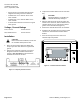
2. Remove the temporary connector cover that is
wrapped around the controller board bracket
(Figure 1). Do not remove the pre-wired FLN
and BLN connectors at this time.
Figure 1. Temporary Connector Cover.
3. Unpack the controller board from the anti-static
bag.
CAUTION:
Improperly aligning or installing the
controller board may damage it.
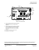
4. With the LEDs and FLN connectors facing the
outside of the enclosure, slide the bottom of the
controller board at a 10
° angle into the bottom
guides on the board bracket (Figure 2).
5. Position the controller board over the standoffs.
6. Straighten the grounding strap so that the spade
connector is not behind the controller board
bracket.
7. Push the memory board cover until each
standoff snaps into position.
FLN0022R1
Figure 2. Controller Board Installation.