
Installation Instructions

Document No. 545-429
Installation Instructions
Rev. 4, September, 2002
Information in this publication is based on current specifications. The company reserves the right to make changes in specifications and
models as design improvements are introduced. Other product or company names mentioned herein may be the trademarks of their
respective owners. © 2002 Siemens Building Technologies, Inc.
Siemens Building Technologies, Inc.
1000 Deerfield Parkway
Buffalo Grove, IL 60089-4513
U.S.A.
Your feedback is important to us. If you have
comments about this document, please send
them to technical.editor@sbt.siemens.com
Document No. 545-429
Printed in the U.S.A.
Page 3 of 3
FLN0045R1
FLN
TX
FLN 1
RX
FLN 2
RX
FLN 3
RX
BLN
TX
BLN
RX
STATUS
BATT
LOW
F
L
N
1
F
L
N
2
F
L
N
3
B
L
N
-
S
+
-
S
+
-
S
+
-
S
+
ON 1
OFF 0
JP2
LISTED
CUS
¤
Underwriters Laboratories Inc.
Smoke Control System Equipment Subassembly
Also suitable for use as:
Energy Management Equipment Subassembly
Also suitable for use as:
Signal System Unit Equipment Subassembly
Also suitable for use as:
Process Management Equipment Subassembly
ISSUE NO. :AG-8256
545765032290015
WARNING:
Power must be ON
when replacing the
battery, otherwise
the cabinet will
coldstart.
Product Part No. 545 793
Refer to Installation Instructions, Part No. 545 429
BPS
(
Bits per second
)
Memory
FLN1
FLN2
FLN3
Modem
MMI
MMI
BLN
TIU
Enabled
BLN #
Controller Board
Field Panel No./Name
Warning: Risk of static discharge.
Turn OFF power beforeremoving or servicing
boards. Use ESD wrist strap when servicing unit.
MMI
Port
MMI
Modem
Port
PART NO.
545 489
For use with System 600 as part of an
engineered smoke control system in accordance
with NFPA 92A. Refer to installation instructions.
PART NOS. 125-1890 Rev. 20 AND 125-1806 Rev.3
N474
CONTROLLER
BOARD
BATTERY
FLN
CONNECTORS
BLN
CONNECTOR
POWER
SWITCH
GROUNDING
SPADE
MMI
PORT
MMI
MODEM
PORT
12
VDC
MEMORY
BOARD
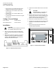
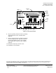
Figure 3. FLN Controller Board.
8. Plug the grounding strap wire into the grounding
spade labeled JP2 on the controller board
(Figure 3).
9. Remove the pre-wired FLN and BLN connectors
from the temporary cover. Plug the connectors
into the corresponding ports on the controller
board labeled FLN 1, FLN 2, FLN 3, and BLN
(Figure 3).
10. Discard the temporary connector cover.
The installation is now complete.