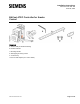
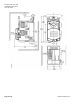
Installation Instructions Document No. 550-163 June 18, 2015 BACnet ATEC Controller for Smoke Control Parts List a. Actuator with pre-terminated tubing b. Position indicator c. Mounting bracket d. Self-tapping mounting screws e. 4 mm hex key f. 3/8 inch shaft adapter (8 to 10 mm shafts) Item No. 550-163 Rev.
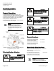
Document No. 550-163 Installation Instructions June 18, 2015 Control Applications CAUTION 6630 through 6637 Equipment damage or loss of data may occur if you do not follow the procedures as specified. Product Description These installation instructions describe directcoupled mounting of the BACnet Actuating Terminal Equipment Controller (ATEC). This is a combination TEC and OpenAir™ GDE131 Non-spring Return Rotary Electronic Damper Actuator.
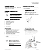
Document No. 550-163 Installation Instructions June 18, 2015 Parts for CE Compliance: Approved 2-RJ11 RTS cable in 25 ft, 50 ft, or 100 ft (7.6 m, 15.2 m, 30.48 m). Installation Instructions 588-100 series Expected Installation Time 1. Determine the size of the damper shaft by doing one of the following: - If the damper shaft is 1/2-inch, proceed to Step 2. NOTE: The actuator comes with a factory installed 1/2-inch damper shaft guide.
Document No. 550-163 Installation Instructions June 18, 2015 2. Determine the damper blade rotation, clockwise or counterclockwise to open. 4. Mark the end of the damper shaft with a pencil/marker. If the blades will rotate counterclockwise, slide the manual override switch to manual, and move the adjustment lever to the right. Return the switch to automatic. If the blades will rotate clockwise, slide the manual override switch to manual, and move the adjustment lever to the left.
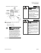
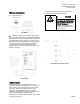
Document No. 550-163 Installation Instructions June 18, 2015 damper blade movement inside the box. WARNING Installations requiring CE Compliance — All wiring for CE rated actuators must be Separated Extra Low Voltage (SELV) or Protective Extra Low Voltage (PELV) per HD384-441. — Use safety-isolating transformers (Class III transformer) per EN 61558. They must be rated for 100% duty cycle. — Over current protection for supply lines is maximum 4A. AVERTISSMENT 10.
Document No. 550-162 Installation Instructions June 18, 2015 Page 6 of 11 Siemens Industry, Inc.
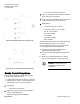
Document No. 550-163 Installation Instructions June 18, 2015 Wiring Instructions 1. Connect the FLN. grounded (at the transformer) then the 24 Vac is considered a floating (isolated source). CAUTION It is important that the neutral that supplies the TEC must be earth grounded at the source of the 24 Vac power. Possible erratic equipment operation or damage if neutral is not grounded. FLN Wiring. 2. Connect the power trunk. DO NOT apply power to the controller without first consulting the specialist.
Document No. 550-163 Installation Instructions June 18, 2015 - 5 VA per DO/ maximum 20 VA total 4. The room temperature sensor (RTS) is installed in the same area as the ATEC. 5. Connection from the ATEC to the field panel is a maximum 4000 feet, 24 AWG minimum. 6. Wiring Range: ATEC with Hot Water Reheat, Fan and Spare DO.
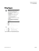
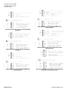
Document No. 550-163 Installation Instructions June 18, 2015 Wiring Diagram NOTE: The controller’s DOs control 24 Vac loads only. The maximum rating is 5 VA for each DO. An external interposing relay is required for any of the following: • VA requirements higher than the maximum • 110 or 220 Vac requirements • DC power requirements • Separate transformers used to power the load (for example part number 540-147, Terminal Equipment Controller Relay Module) Application 6630 VAV Cooling Only Wiring Diagram.
Document No. 550-163 Installation Instructions June 18, 2015 Application 6633 VAV with One Hot Water Valve Wiring Diagram. Application 6631 VAV Cooling and Heating Wiring Diagram. Application 6632 VAV with Electric Heat Wiring Diagram. Application 6632 VAV with Baseboard Radiation Wiring Diagram. Page 10 of 11 Application 6633 VAV with Two Hot Water Valves Wiring Diagram. Application 6634/6636 VAV Series Fan or Parallel Fan and Electric Heat Wiring Diagram. Siemens Industry, Inc.
Document No. 550-163 Installation Instructions June 18, 2015 Application 6635/6637 VAV Series Fan or Parallel Fan and Hot Water Heat Wiring Diagram. Information in this document is based on specifications believed correct at the time of publication. The right is reserved to make changes as design improvements are introduced. Product or company names mentioned herein may be the trademarks of their respective owners. © 2015 Siemens Industry, Inc. Siemens Industry, Inc. Your feedback is important to us.