
Installation Instructions

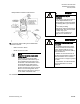
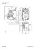
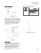
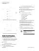
Table Of Contents

Document No. 550-163
Installation Instructions
June 18, 2015
Siemens Industry, Inc. 5 of 11
damper blade movement inside the box.
10. Connect the airflow tubing for the Differential
Pressure Sensor.
- RED connects to HIGH.
- BLUE connects to LOW.
NOTE:
Suggested use of the 3-part serial
number labels:
Remove one of the
self-adhesive controller ID labels
(three part label located at the top of
the controller board) and place it on
the bottom of the terminal box next to
the Terminal Box ID. Remove the
second tear-off label and place it on
the box schedule next to the Terminal
Box ID. The remaining label can be
added to a floor plan layout, job log or
on the inside of the RTS cover.
The installation is complete.
WARNING
Installations requiring CE
Compliance
— All wiring for CE rated actuators
must be Separated Extra Low
Voltage (SELV) or Protective Extra
Low Voltage (PELV) per HD384-4-
41.
— Use safety-isolating
transformers (Class III transformer)
per EN 61558. They must be rated
for 100% duty cycle.
— Over current protection for
supply lines is maximum 4A.
AVERTISSMENT
Installations avec confirmité aux
normes CE
— Le câblage d’actionneurs mis à
la norme CE doit être à très basse
tension séparée (SELV) ou très
basse tension de protection (PELV),
selon HD384-4-41.
— Utilisez des transformateurs de
sécurité (transformateurs Classe III)
selon EN 61558. Ceux-ci doivent
fonctionner avec un rapport cyclique
de 100%.
— La protection de surintensité des
lignes d’alimentation est de 4A
maximum.