
Installation Instructions

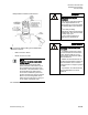
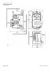
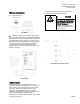
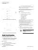
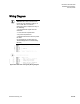
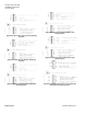
Table Of Contents

Document No. 550-163
Installation Instructions
June 18, 2015
Page 8 of 11 Siemens Industry, Inc.
ATEC with Hot Water Reheat, Fan and Spare DO.
Wiring for AI / DI 10K/100K Selectable Thermistor.
Smoke Control Compliance
The following instructions and information apply if
used for smoke control sequence.
1. Install Smoke Control Listed products, enclosure
and transformer. See the
Product Numbers
and
Accessories
sections for more information.
2. Input Rating:
- 24V 60 Hz 5 VA maximum
3. Digital Output (DO) are only I/O authorized for
smoke control applications.
Digital Output (DO) Electrical Ratings:
- 5 VA per DO/ maximum 20 VA total
4. The room temperature sensor (RTS) is installed
in the same area as the ATEC.
5. Connection from the ATEC to the field panel is a
maximum 4000 feet, 24 AWG minimum.
6. Wiring Range:
- Transformer: primary 14 AWG
- 24 Vac Input Power: 14 to 18 AWG
- DO: AI: 18 to 20 AWG
- AO: 18 to 20 AWG
- DI: 18 AWG
- LAN: 20 to 24 AWG
- RST: 24 AWG
All circuits are power limited; FLN is RS-485, RTS is
RS-232. Digital Inputs (DI) are dry contacts.
See the following documents for more information
on configuring smoke control applications:
Smoke Control Systems Application and
Engineering Manual (
125-1806)
Smoke Control System Application Guide (
125-
1816)
NFPA and UL Standards Relevant to Smoke
Control System Application Guide (
125-1817)
NOTE:
The 24 Vac relay module is not
applicable for smoke control
application.