
Installation Instructions

540-204
Installations Instructions
Rev. 2, 1/99
P
PP
Pa
aa
age
ge ge
ge 2
22
2
o
oo
of
f f
f 8
88
8
Siemens Building Technologies, Inc.
Landis Division
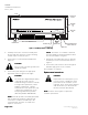
24 V-AC
LAN
TRUNK
COVER
BST
CH
+-
SRXTX RTS
DO 1 DO 2 DO 3 DO 4 DO 5 DO 6
NO C NO C NO C NO C NO C NO C
DO 7
NO C
DO 8
NO C
DI 3 DI 2
AI 3 + -
AO 1DI 4
1 2 3 4 5 6 7 8 9 10 11 12 13 14 15 16 17 18 19 20 21 22 23 24
1 2 3 4 5 6 7 8 9 10 11 12 13 14 15 16 17 18 19 20 21 22 23 24
CONTROLLER
BOARD
POWER
TRUNK
TERMINATIONS
TRANSMIT LED
RECEIVE LED
BST LED
LAN
TRUNK
TERMINATIONS
INPUT / OUTPUT TERMINATIONS
DO LEDS
MOUNTING
HOLE
(2)
MOUNTING
RAIL
ROOM TEMPERATURE
SENSOR / MMI PORT
TEC0167R3
CH
+-
S
F
FF
Fi
ii
igu
gugu
gur
rr
re
e e
e 1
11
1.
. .
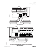
. H
HH
He
ee
ea
aa
at
t t
t P
PP
Pu
uu
um
mm
mp
p p
p C
CC
Con
onon
ontr
trtr
tro
oo
oll
llll
lle
ee
er
r r
r –
– –
– M
MM
Mu
uu
ul
ll
lt
tt
ti
ii
i-
--
-S
SS
St
tt
ta
aa
age
gege
ge.
..
.
4. Carefully remove the controller assembly from
the anti-static bag. Center it over the mounting
rail and snap it securely into place.
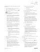
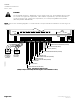
5. Connect the Local Area Network (LAN) trunk
(Figure 3).
CA
CACA
CAU
UU
UT
TT
TI
II
IO
OO
ON
NN
N:
::
:
Do not connect an earth ground to the
Shield (S) terminal.
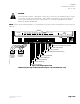
6. Connect the point wiring for the appropriate
application. Refer to Figures 5 through 6.
CA
CACA
CAU
UU
UT
TT
TI
II
IO
OO
ON
NN
N:
::
:
The Controller’s Digital Outputs (DOs)
control 24 Vac loads only. The
maximum rating is 12 VA for each DO.
For higher VA requirements, 110 or
220 Vac requirements, separate
transformers used to power the load,
or DC power requirements, use an
interposing 220 V 4-relay module
(TEC Relay Module P/N 540-147).
N
NN
NO
OO
OT
TT
TE
EE
E:
::
: Each DO provides a Normally Open (NO)
and a Common (C) terminal. Terminate both
connections of a 24 Vac load directly to the
controller board. Actuators use 2 DOs and
require 3 connections.
N
NN
NO
OO
OT
TT
TE
EE
E:
::
: The 24 Vac “H” terminal is switched
through a TRIAC to the NO terminations when
the associated DO is energized.
7. Plug the Room Temperature Sensor cable into
the RTS port on the controller board. Refer to
Figure 1.
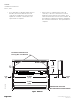
8. Connect the power trunk as shown in Figure 4.
DO NOT apply power to the controller.
The installation is complete.
R
RR
Rep
epep
epl
ll
lac
acac
ace
ee
em
mm
men
enen
ent
t t
t I
II
In
nn
ns
ss
str
trtr
tru
uu
uc
cc
ct
tt
ti
ii
ion
onon
ons
ss
s
CA
CACA
CAU
UU
UT
TT
TI
II
IO
OO
ON
NN
N:
::
:
Replacement of a TEC requires you to
record, re-enter, or update the initial
point values of the controller you are
replacing. These are the points marked
with an asterisk (*) on the Controller
Interface Software (CIS) display.
N
NN
NO
OO
OT
TT
TE
EE
E:
::
: CIS Rev. 2.0 or higher is required for
controller replacement.