
Installation Instructions

Rev. 2, 4/97 Installation Instruction 545-434
Copyright
1997 by Landis & Staefa, Inc. • Printed in U.S.A.Page 1 of 2
INSTALLATION INSTRUCTIONS
FLN Controller Board Bracket Assembly
PRODUCT DESCRIPTION
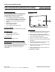
The FLN Controller Board Bracket Assembly (refer to
Figure 1) provides the means for mounting the FLN
Controller Board (545-793) in an existing LAN
Controller enclosure. This kit contains:
FLN Controller Board Bracket mounting plate
Four removable terminal blocks (wire connectors)
Two #6-32 x 5/16-inch Phillips pan-head screws
Two 5/16-inch rivet edge holding circuit board
supports
Three 3/8-inch push spacers
One 1/4-inch push spacer
FLN Controller Board grounding wire
PRODUCT NUMBER
545-135 FLN Controller Board Bracket Assembly
REQUIRED TOOLS
Small flat-blade screwdriver
Medium Phillips-head screwdriver
Volt-ohm meter
PREREQUISITES
LAN Controller enclosure in place
PLACEMENT AND SMOKE CONTROL SYSTEM
REQUIREMENTS
Refer to the Field Panel section of the Understanding
Powers System 600 Manual (125-1890) and the Smoke
Control Application and Engineering Manual (125-
1806) for placement and smoke control system
requirements.
INSTALLATION TIME
20 minutes
FLN0032R1
Figure 1. FLN Controller Board Bracket.
INSTRUCTIONS
1. Verify that the existing LAN Controller enclosure in
which the bracket will be mounted is grounded.
2. Prior to removing the existing LAN Controller
electronic board assembly, label any of the wiring
(FLN trunk lines or BLN trunk lines).
3. Remove the transformer and TIU (if installed).
4. Remove the FLN Controller Board Bracket from the
packaging.
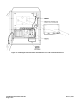
5. Locate the mounting holes for the TIU in the LAN
Controller Enclosure (refer to Figure 2).
6. Align the bracket with the ledge at the bottom and
center it over these holes.
7. Secure the bracket to the enclosure with the two
Phillips pan-head screws.
The installation is complete.