
Installation Instructions

Installation Instructions
Document No. 540-570
July 15, 2009
Smoke Control
Listed Constant Volume Controller — Electronic
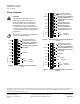
Output
24 V-AC
CH
CH
DO 1 DO 2 DO 3 DO 4 DO 5
NO C NO C NO C NO C NO C
DO 6 DI 3 DI 2 FLN
TRUNK
NO C
POWER
TRUNK
TERMINATIONS
FLN TRUNK
TERMINATIONS
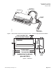
MOUNTING
HOLE
(2)
CONTROLLER
BOARD
COVER
MOUNTING
RAIL
DO LEDS
INPUT/OUTPUT TERMINATIONS
TRANSMIT LED
RECEIVE LED
AI 3
TX RX + - S
+-
S
BST RTS
1 2 3 4 5 6 7 8 9 10 11 12 13 14 15 16
1 2 3 4 5 6 7 8 9 10 11 12 13 14 15 16
TEC0200-SR1
BST LED ROOM TEMPERATURE
SENSOR/MMI PORT
AIR VELOCITY
SENSOR PORTS
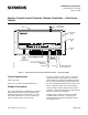
Figure 1. Smoke Control Listed Constant Volume Controller — Electronic Output.
Control Applications
2030, 2032, 2033
2130, 2132, 2133 (Secure Mode Applications)
Product Description
The Terminal Equipment Controller (TEC) provides
high performance DDC of pressure-independent,
variable-air-volume zo ne -level rout ine s. The TEC
can operate stand-alone or can be networked to
perform complex HVAC control functions.
TheTECcanalsobeusedaspartofaSiemens
engineered smoke control system. The TEC are
used to initiate the operations of dampers and fans
but the smoke control strategy will be initiated from
any of the APOGEE field panels and not by the TEC.
These instructions explain how to field install or
replace a Smoke Co ntrol Listed Constant Volume
Controller — Electro nic Output with or without Secure
Mode or optional Autozero Module.
Shipping carton includes a controller assembly
(controller board and cover), a mounting rail,
Autozero Module and bracket (optional), and two
self-tapping screws.
I
tem Number: 540-570, Rev. CA
P
age 1 of 6