
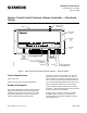
Installation Instructions

Document No. 540-570
Installation Instructions
July 15, 2009
• 1/4-inch (6.35 mm) hex nut bit
Prerequisites
• Unit Conditioner installed
• 24 Vac C las s 2 power source
• Supply power to the unit is OFF
• If required, controller enclosure installed
• Room temperature sensor installed (optional).
(If desired, a low-cost temporary temperature
sensor is available that plugs into the RTS
port of the TEC (P/N 540-658P25), providing
temperature input and actual space control
until the permanent room or duct sensor is
installed.)
If the controller is be in g installed on a box
with 1 or m ore stages of electric heat,
the 550 -809 MOV w ith pre-terminated
spade connectors must be installed across
the manufacturer-supplied airflow switch.
MOV’s can be installed at the time the
controller is factory mounted; coordinate
with the box manufacturer prior to order
placement. For field installation, reference
document 540-986.
Instructions
All wiring must conform to NEC an d local
codes and regulations.
Transformer Installation for Smoke
Control Applications
P/N 5041MWCB and 10041MWCB
1. Mount the transfo rmer to a facility installed UL
Listed junction box (2x4 or 4x4).
Mount the integral conduit nipple through the
knock-out on the junction box.
2. Connect the secondary wires to the TEC using
UL Listed CL2 or equivalent cables.
P/N KELE AM-2483-OA
1. Use Siemens re ce ptacle box assemb ly (P/N
529-804), installed only inside the enclosure (P/N:
550-002K).
2. Plug the transformer (P/N KELE AM-2483-OA) in
to the rec eptacle.
3. Connect the secondary wires to the TEC using
UL Listed CL2 or equivalent cables.
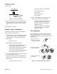
Controller Installation
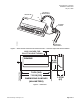
1. Secure the mounting rail (Figure 1) in the
controller’s desired location.
2. Place the ESD wrist strap on your wrist and attach
it to a good earth ground.
3. Remove the controller from the static proof bag
and snap it into place on the mounting rail.
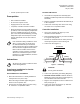
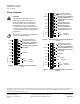
4. Connect the FLN (Figure 2).
FLN TRUNK
+-
S
(SHIELD) (SHIELD)
(+)
(+)
(-)
(-)
TEC0470R1
Figure 2. FLN Wiring.
CAUTION:
Do not ground the shield.
5. Connect the point wiring (see Wiring Diagrams).
6. 540-104K and 540-104CK: Install the Autozero
Module and connect the wires to DO6 (Figure 5).
See installation instructions 540-199.
7. Plug the room temperature sensor cable into the
RTS port (Figure 1).
8. Connect the power trunk (Figure 3). DO NOT
apply power to the controller.
Siemens Building Technologies, Inc. Page 3 of 6