
Installation Instructions

Document No. 540-570
Installation Instructions
July 15, 200 9
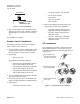
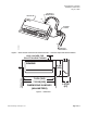
C H
24 V COMMON
24 V HOT
POWER TRUNK
TEC0508R1
Figure 3. Power Trunk Wiring.
9. Connect the tubing from the air velocity sensor
pickups to the ports on the controller or Autozero
Module (Figure 5). Connect HI to HI and LO to
LO.
The installation is complete.
Smoke Control Compliance
The following instruction and information apply if
used for smoke control sequence.
1. If used for Smo ke Control, install Smoke C
ontrol
Listed product, enclosure and transfor
mer (see
Product Numbers and Accessories secti
ons).
2. Input Rating:
• 24V 60 HZ 42 VA
Digital Output (DO) Electrical Ratings:
• Transformer P/N 5041BCWB: maximum
6VA per DO/ maximum 30 VA total.
• Transformer P/N 10041BCWB: maximum
6VA per DO/ maximum 36 VA total.
• Transformer P/N AM-2483-OA: max
imum
6VA per DO/ maximum 16 VA total.
3. The room temperature sensor (RTS) is installed
inthesameroomastheTEC.
4. Connection from the TEC to the A
POGEE field
panel is maximum 4000 feet, 24
AWG minimum.
5. Wiring Range:
• Transformer: primary 14 AW G
• 24 Vac Input Power: 14 to 18 AWG
• DO:AI:18to20AWG
•DI:18AWG
• LAN:20to24AWG
•RST:24AWG
6. Refer to the following documents when used
configuring for smoke control application:
• 125-1806: Smoke C ontrol Systems
Application and Engineering Manual
• 125-1816: Smoke Control System
Application Guide
• 125-1817: NFPA and UL Standards
Relevant to Smoke Control System
Application Guide
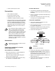
CE Compliance
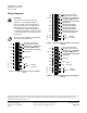
If CE comp lian ce is required, a ferrite filter must be
placed approximately 1–2 cm from the end of the
cable being shielded (RTS cable and point wiring for
AI3) (Figure 4).
TEC0320R3
1- 2 cm
1
Place the filter 1-2 cm
from the end of the cable
or wiring to be shielded.
2
Wind the cable tightly
twice around the filter.
3
Close the filter and wrap
with a zip tie.
Figure 4. Ferrite filter(s) fo
r CE Compliance.
Page 4 of 6
Siemens Building Technologies, Inc.