TEC Controller Constant Volume - Cooling Only, Application 2030 Application Note 140-1021 2015-08-07 Building Technologies
Table of Contents Overview ............................................................................................................................. 4 Hardware Inputs .................................................................................................................. 5 Hardware Outputs ................................................................................................................ 5 Secure Mode Operation.......................................................................
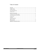
Overview Hardware Inputs Overview In Application 2030, the controller provides a constant volume of air to the room during occupied periods, and a lower constant volume of air to the room during unoccupied periods. Application 2030 Control Drawing. Application 2030 Control Schedule. 4 Siemens Industry, Inc.
Overview Hardware Inputs Hardware Inputs Analog Air velocity sensor Room temperature sensor (Optional) Auxiliary temperature sensor (100K thermistor) Application 2030 supports a room temperature sensor for monitoring purposes only.
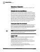
Sequence of Operation Occupied and Unoccupied Modes Sequence of Operation The following paragraphs present the sequence of operation for Application 2030 -Cooling Only. Occupied and Unoccupied Modes The occupied/unoccupied status of the space is determined by the status of OCC.UNOCC. The control of this point differs depending on whether the controller is monitoring the status of a wall switch or if the controller is connected to a field panel.
Sequence of Operation Calibration Example If UNOCC FLOW = 250 cfm, and if OCC FLOW = 1000 cfm then, in unoccupied mode the FLOW STPT = (250 cfm ÷ 1000 cfm) × 100% flow = 0.25 × 100% flow = 25% flow Since 250 cfm is 25% of 1000 cfm, the flow setpoint in unoccupied mode is 25%. UNOCC FLOW can be set less than or equal to, but not greater than OCC FLOW. Calibration Calibration of the controller’s internal air velocity sensor(s) is periodically required to maintain accurate air velocity readings.
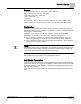
Sequence of Operation Application Notes Application Notes If FLOW is oscillating while FLOW STPT is constant, then the flow loop requires tuning. The controller, as shipped from the factory, keeps all associated equipment OFF. Spare DOs can be used as auxiliary points that are controlled by the field panel after being defined in the field panel’s database. The combination of DO 3 and DO 4 may be used as auxiliary motor points.
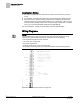
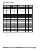
Application 2030 Point Database Application 2030 Point Database Point Number Descriptor Factory Default (SI Units) Eng Units (SI Units) Slope (SI Units) Intercept (SI Units) On Text Off Text 1 CTLR ADDRESS 99 -- 1 0 -- -- 2 APPLICATION 2092 -- 1 0 -- -- {04} ROOM TEMP 74.0 (23.44888) DEG F (DEG C) 0.25 (0.14) 48.0(8.88888) -- -- {15} AUX TEMP 74.0 (23.495556 ) DEG F (DEG C) 0.5 (0.28) 37.5(3.
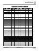
Application 2030 Point Database Point Number Descriptor Factory Default (SI Units) Eng Units (SI Units) Slope (SI Units) Intercept (SI Units) On Text Off Text ANG 57 DPR2 ROT ANG 90 -- 1 0 -- -- 58 MTR SETUP 0 -- 1 0 -- -- 59 DO DIR.REV 0 -- 1 0 -- -- 71 FLOW P GAIN 0.25 -- 0.05 0 -- -- 72 FLOW I GAIN 0.018 -- 0.001 0 -- -- 73 FLOW D GAIN 0 -- 2 0 -- -- 74 FLOW BIAS 50 PCT 0.4 0 -- -- {75} FLOW 0 PCT 0.25 0 -- -- {78} CTL TEMP 74.
Issued by Siemens Industry, Inc. Building Technologies Division 1000 Deerfield Pkwy Buffalo Grove IL 60089 Tel. +1 847-215-1000 Document ID 140-1021 Edition 2015-08-07 © Siemens Industry, Inc., 2015 Technical specifications and availability subject to change without notice.