
Application

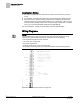
Table Of Contents

Sequence of Operation
Occupied and Unoccupied Modes
6
Siemens Industry, Inc. Application Note, App 2030 140-1021
2015-08-07
Sequence of Operation
The following paragraphs present the sequence of operation for Application 2030 --
Cooling Only.
Occupied and Unoccupied Modes
The occupied/unoccupied status of the space is determined by the status of
OCC.UNOCC. The control of this point differs depending on whether the controller is
monitoring the status of a wall switch or if the controller is connected to a field panel.
When a wall switch is physically connected to the termination strip on the controller at
DI 2 and WALL SWITCH = YES, the controller monitors the status of DI 2. When the
status of DI 2 is ON (the switch is closed), OCC.UNOCC is set to OCC indicating that
the controller is in occupied mode. When the status of DI 2 is OFF (the switch is open),
OCC.UNOCC is set to UNOCC indicating that the controller is in unoccupied mode.
When WALL SWITCH = NO, the controller does not monitor the status of the wall
switch, even if one is connected to it. In this case, if the controller is operating stand-
alone, the controller stays in occupied mode all the time. If the controller is operating
with centralized control (connected to a field panel), the field panel can send an
operator or PPCL command to override the status of OCC.UNOCC.
Unoccupied Mode Override Switch
If an override switch is present on the room temperature sensor and a value (in hours)
other than zero has been entered into OVRD TIME, then by pressing the override
switch, a room occupant can reset the controller to occupied mode for the length of
time set in OVRD TIME. The status of UNOCC OVRD changes to OCC and remains
there until OVRD TIME elapses, at which point UNOCC OVRD changes back to
UNOCC and the controller returns to unoccupied mode.
NOTE:
Only during unoccupied mode (MODE = Unoccupied) can a room sensor’s override
switch set the controller to occupied mode; if MODE equals anything other than
Unoccupied, UNOCC OVRD will equal UNOCC.
Control Loops
Flow Loop – maintains the point FLOW STPT by modulating the supply air damper
point, DMPR COMD. The flow loop maintains the airflow at either OCC FLOW or
UNOCC FLOW depending on the value of OCC.UNOCC.
To enhance stable flow control, an advanced algorithm is used to calculate a
controllable setpoint as the value approaches zero cfm (lps).
FLOW is the input value for the flow loop. It is calculated as a percentage based on
where AIR VOLUME is between 0 cfm (LPS) and OCC FLOW. In the following text,
this percentage is referred to as % flow.
If AIR VOLUME equals 0 cfm (LPS), then FLOW is 0% flow.
If AIR VOLUME equals OCC FLOW, then FLOW is 100% flow.
The FLOW STPT percentage that corresponds to UNOCC FLOW is calculated as:
(UNOCC FLOW ÷ OCC FLOW) × 100% flow.