APOGEE Unit Vent Controller ⎯ 0 to 10V Output Owner’s Manual 125-1957 Rev. CA, July 2007 Siemens Building Technologies, Inc.
Rev. CA, July 2007 NOTICE The information contained within this document is subject to change without notice and should not be construed as a commitment by Siemens Building Technologies, Inc. Siemens Building Technologies, Inc. assumes no responsibility for any errors that may appear in this document. All software described in this document is furnished under a license and may be used or copied only in accordance with the terms of such license.
Table of Contents How To Use This Manual................................................................................................. iv Manual Organization ......................................................................................................iv Manual Conventions ................................................................................................... v Manual Symbols ..........................................................................................................
APOGEE Unit Vent Controller⎯0 to 10V Output Owner’s Manual Point Database ................................................................................................................ 23 Troubleshooting .............................................................................................................. 33 Overview ...................................................................................................................... 33 Basic Service Information ..................................
Table of Contents iii
How To Use This Manual This manual is written for the owner and user of the Siemens Building Technologies, Inc. Unit Vent Controller – 0 to 10V, often referred to as controller for the remainder of this manual. This manual is designed to help you become familiar with the controller and its applications. This chapter covers manual organization, manual symbols and conventions used and how to access help.
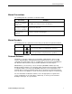
Manual Organization Manual Conventions The following table lists conventions used in this manual. Convention Actions that you should perform are specified in boldface font. Example Type F for Field panels. Click OK to save changes and close the dialog box. Error and system messages are displayed in Courier New font. The message Report Definition successfully renamed appears in the status bar. New terms appearing for the first time are italicized.
APOGEE Unit Vent Controller⎯0 to 10 V Output Owner’s Manual Getting Help For more information about the Unit Vent Controller, contact your local Siemens Building Technologies representative. Where To Send Comments Your feedback is important to us. If you have comments about this manual, please submit them to SBT_technical.editor.us.sbt@siemens.com vi Siemens Building Technologies. Inc.
1 Product Overview Introduction The Unit Vent Controller—0 to 10V Output is the Siemens Building Technologies, Inc. Terminal Equipment Controller (TEC) used in unit ventilator applications. See Figure 1. It provides Direct Digital Control (DDC) for five applications. The controller can operate as an independent, stand-alone, DDC room controller or be networked with an APOGEE field panel. The controller provides all termination, input/output, system and local communication connections. See Figure 1.
APOGEE Unit Vent Controller⎯0 to 10V Output Owner’s Manual COVER CONTROLLER BOARD MOUNTING HOLE (2) 24 V-AC TEC0197R3 C H C H DO 1 DO 2 DO 3 DO 4 DO 5 DO 6 DO 7 DO 8 DI 3 NO C NO C NO C NO C NO C NO C NO C NO C AI 3 DI 2 DI 4 LAN TRUNK AO 1 AO 2 AO 3 + - + - + - 1 2 3 4 5 6 7 8 9 10 11 12 13 14 15 16 17 18 19 20 21 22 23 24 25 26 27 28 1 2 3 4 5 6 7 8 9 10 11 12 13 14 15 16 17 18 19 20 21 22 23 24 25 26 27 28 TX RX + - S + - BST MOUNTING RAIL RTS S DO LEDS POWER TRUNK TERMINATIONS
Introduction Hardware Outputs Analog (0 to 10V) Application • Cooling valve actuator 2281, 2283, 2287 • Face-bypass damper actuator 2281, 2283, 2284, 2286 • Heating valve actuator 2281, 2283, 2284, 2286, 2287 • Outdoor air damper actuator 2281, 2283, 2284, 2286 Application Digital • Auxiliary radiation electric coil contact; or, auxiliary radiation two-position valve actuator 2281, 2283, 2284, 2286 • Unit fan 2281, 2283, 2284, 2286, 2287 • First stage electric heat 2281, 2283, 2284,
APOGEE Unit Vent Controller⎯0 to 10V Output Owner’s Manual FLN TRUNK 24 V-AC E C H DO 1 DO 2 DO 3 DO 4 DO 5 NO C NO C NO C NO C NO C NO + - S 1 2 3 4 5 6 7 8 9 10 11 1 1 2 3 4 5 6 7 8 9 10 11 12 (SHIELD) TEC0470R1 COMMON TEC0253R2 24 VAC HOT CONTROLLER POWER WIRING (SHIELD) (-) (+) (-) (+) NOTE: NO EARTH GROUND CONNECTION Figure 2. Power Wiring. Figure 3. Communication Wiring. Controller LED Indicators The controller has eleven Light Emitting Diode (LED) indicators. See Figure 1.
Introduction Mixed Air/Discharge Air Temperature Sensor The mixed air/discharge air temperature sensor is a 100K ohm thermistor that connects to the controller at the screw terminals for Al 3. For more information about Siemens Building Technologies, Inc. temperature sensors, contact your local Siemens Building Technologies, Inc. representative.
2 Applications Basic Operation The Unit Vent Controller⎯0 to 10V Output provides Direct Digital Control (DDC) technology for unit ventilator applications.
Basic Operation Day Cooling Operation The controller maintains the room temperature by resetting the unit ventilator's discharge temperature setpoint (2281), running the face-bypass damper at full all the time, modulating or cycling the available coil control device (DX coil – 2284) or positioning the outdoor air damper. Night Heating Operation The controller maintains the room temperature turning the fan and heating on and off as required.
APOGEE Unit Vent Controller⎯0 to 10 V Output Owner’s Manual Cooling Loop – maintains room temperature setpoint by turning valves on and off and using free cooling (mixed air control) when available. Auxiliary Loop – modulates the auxiliary loop using the auxiliary setpoint and discharge setpoint (2284). Mixed Air Loop – modulates the mixed air loop using the mixed air setpoint and mixed air temperature (2283). DX Loop – modulates the cooling loop using the control setpoint and room temperature (2284).
Basic Operation If the room temperature sensor input to the Unit Vent Controller fails or the LTDT equals ON, the controller goes through the following shutdown sequence: • Outdoor air damper is closed. • Heating is full ON (except electric, which is OFF). • Cooling is full OFF. • Face-bypass damper is open to face. • Fan is OFF. • Auxiliary radiation is OFF. • Two-position heating valve actuator is open. • Two -position cooling valve actuator is closed.
APOGEE Unit Vent Controller⎯0 to 10 V Output Owner’s Manual Application 2281 – Heating and/or Chilled Water Cooling, ASHRAE Cycles I and II In Application 2281, the Unit Vent Controller⎯0 to 10V Output controls a unit ventilator equipped with a chilled water coil for cooling, and/or a heating coil, which may be hot water, steam, or electric, for ASHRAE Cycles I and II. A face-bypass damper can be controlled, replacing both the modulating (0-10V) heating and cooling actuators.
Application 2281 – Heating and/or Chilled Water Cooling, ASHRAE Cycles I and II Figure 5. Application 2281 Control Drawing. Figure 6. Application 2281 Control Drawing. Siemens Building Technologies, Inc.
APOGEE Unit Vent Controller⎯0 to 10 V Output Owner’s Manual Figure 7. Application 2281 Control Drawing. Figure 8. Application 2281 Control Drawing. NOTE: 12 The auxiliary radiation is an independent loop and is not sequenced with the other control loops. Siemens Building Technologies. Inc.
Application 2283 – Heating and/or Chilled Water Cooling, ASHRAE Cycle III Application 2283 – Heating and/or Chilled Water Cooling, ASHRAE Cycle III In Application 2283, the Unit Vent Controller⎯0 to 10V Output controls a unit ventilator equipped with a chilled water coil for cooling, and/or a heating coil, which may be hot water, steam or electric, for ASHRAE Cycle III. A face-bypass damper can be controlled, replacing both the modulating (0-10V) heating and cooling actuators.
APOGEE Unit Vent Controller⎯0 to 10 V Output Owner’s Manual Figure 10. Application 2283 Control Drawing. Figure 11. Application 2283 Control Drawing. 14 Siemens Building Technologies. Inc.
Application 2283 – Heating and/or Chilled Water Cooling, ASHRAE Cycle III Figure 12. Application 2283 Control Drawing. Figure 13. Application 2283 Control Drawing. Siemens Building Technologies, Inc.
APOGEE Unit Vent Controller⎯0 to 10 V Output Owner’s Manual Application 2284 – Heating and DX Cooling, ASHRAE Cycles I and II In Application 2284, the Unit Vent Controller⎯0 to 10V output controls a unit ventilator equipped with a DX coil for cooling, and/or a heating coil, which may be hot water, steam, or electric, for ASHRAE Cycles I and II. A face-bypass damper can be controlled, replacing the modulating (0-10V) heating actuator, but will modulate only in heating mode.
Application 2284 – Heating and DX Cooling, ASHRAE Cycles I and II Figure 15. Application 2284 Control Drawing. Figure 16. Application 2284 Control Drawing. NOTE: The auxiliary radiation is an independent loop and is not sequenced with the other control loops. Siemens Building Technologies, Inc.
APOGEE Unit Vent Controller⎯0 to 10 V Output Owner’s Manual Application 2286 - Heating and DX Cooling, ASHRAE Cycle III In Application 2286, the Unit Vent Controller—0 - 10V Output controls a unit ventilator equipped with a DX coil for cooling, and/or a heating coil, which may be hot water, steam, or electric, for ASHRAE Cycle Ill. A face-bypass damper can be controlled, replacing the modulating (0-10V) heating actuator, but will modulate only in heating mode.
Application 2286 - Heating and DX Cooling, ASHRAE Cycle III Figure 18. Application 2286 Control Drawing. Figure 19. Application 2286 Control Drawing. Siemens Building Technologies, Inc.
APOGEE Unit Vent Controller⎯0 to 10 V Output Owner’s Manual Application 2287 – Heating and Cooling, Nesbitt Cycle W Overview In Application 2287, the Unit Vent Controller⎯0-10V Output controls a unit ventilator equipped with a heating coil, which may be hot water or steam, for Nesbitt Cycle W. Auxiliary radiation coils are piped parallel to the heating coil and are not controlled separately by the application. A chilled water coil or a DX cooling coil may be controlled.
Application 2287 – Heating and Cooling, Nesbitt Cycle W Figure 21. Application 2287 Control Drawing. Figure 22. Application 2287 Control Drawing. Siemens Building Technologies, Inc.
APOGEE Unit Vent Controller⎯0 to 10 V Output Owner’s Manual Application 2299 – Slave Mode Overview Application 2299 is the slave mode application for the Unit Vent Controller—0 - 10V Output (P/N 540-509). Slave mode is the default application that comes up when power is first applied to the controller. Slave mode provides no control.
3 Point Database This chapter presents a description of the Unit Vent Controller database including point descriptors, point addresses, and a listing of applications in which each point is found. Table 3. Point Database. Descriptor Address Application Description CTLR ADDRESS 01 2281, 2283, 2284, 2286, 2287, 2299 Identifies the controller on the FLN trunk. APPLICATION 02 2281, 2283, 2284, 2286, 2287, 2299 The identification number of the program running in the controller.
APOGEE Heat Pump Controller—Multi Stage Owner's Manual Descriptor Address Application Description RM STPT MIN 11 2281, 2283, 2284, 2286, 2287 The minimum temperature setpoint in degrees that the controller can use from the setpoint dial. This overrides any temperature setpoint from the setpoint dial that falls below this minimum.
Application 2299 – Slave Mode Descriptor Address Application Description OVRD TIME 20 2281, 2283, 2284, 2286, 2287 The amount of time (in hours) that the controller will operate in day mode, when the override switch is pressed, while the controller is in night mode. NGT OVRD 21 2281, 2283, 2284, 2286, 2287 Indicates the mode that the controller is operating in with respect to the override switch. NIGHT indicates that the switch has not been pressed and the override timer is not active.
APOGEE Heat Pump Controller—Multi Stage Owner's Manual Descriptor Address Application Description AOV1SPAN 31 2281, 2283, 2284, 2286, 2287 Indicates the width of the voltage range where the actuator, controlled by AO1, moves. AOV1START 32 2281, 2283, 2284, 2286, 2287 Indicates the lower end of the voltage range where the actuator, controlled by AO1, moves. AOV2 SPAN 33 2281, 2283, 2284, 2286, 2287 Indicates the width of the voltage range where the actuator, controlled by AO2, moves.
Application 2299 – Slave Mode Descriptor Address Application Description DX 44 2284, 2286, 2287 The actual status of the DX cooling compressor. DO 5 45 2287, 2299 Digital output 5 controls a 24 Vac load with an ON or OFF status. EHEAT 1 45 2281, 2283, 2284, 2286 The actual status of the first stage of electric heat. DO 6 46 2287, 2299 Digital output 6 controls a 24 Vac load with an ON or OFF status.
APOGEE Heat Pump Controller—Multi Stage Owner's Manual Descriptor Address Application Description CLG OUTPUT 61 2281, 2283, 2284, 2286, 2287 If the cooling control device is not DX, then the value of this point indicates the position of the cooling actuator. If DX cooling is used, then the value of this point determines whether DX is ON or OFF. Valid values: 0 to 100% OA DMPR POS 62 2281, 2283, 2284, 2286, 2287 Indicates the position of the outdoor air damper actuator.
Application 2299 – Slave Mode Descriptor Address Application Description MA LOOPOUT 77 2283, 2286 The mixed air control loop output value that is used to determine OA DMPR POS (Point 62). OA LOOPOUT 77 2287 The outdoor air damper control loop output valve that is used to determine OA DMPR POS (Point 62). CTL TEMP 78 2281, 2283, 2284, 2286, 2287 The temperature used as input for the temperature control loops.
APOGEE Heat Pump Controller—Multi Stage Owner's Manual Descriptor Address Application Description NGT DBAND 88 2281, 2283, 2284, 2286, 2287 During night mode, this point indicates the number of degrees above or below (depending on heating/cooling mode) the night setpoint that the room temperature can raise or drop before the fan will be turn ON.
4 Troubleshooting Overview This chapter describes corrective measures you can take should you encounter a problem when using a Unit Vent Controller. You are not required to do any controller troubleshooting. You may want to contact your local Siemens Building Technologies representative if a problem occurs or you have any questions about the controller. NOTE: When troubleshooting, record what the problem is and what actions were performed immediately before the problem occurred.
APOGEE Heat Pump Controller – Multi-Stage Owner's Manual Ordering Replacement Parts If a controller is not operating correctly, order a new controller. The product number for ordering a replacement controller is the controller product number preceded by an "R".
Glossary Overview The glossary contains terms and acronyms that are used in this manual. For definitions of point database descriptors, see Chapter 3, Point Database. For definitions of commonly used terms as well as acronyms and abbreviations associated with the APOGEE Automation System, see the Siemens Building Technologies Technical Glossary of Building Controls Terminology and Acronyms, (125-2185). This book is available from your local Siemens Building Technologies representative. Al Analog Input.
APOGEE Unit Vent Controller⎯0 to 10V Output Owner’s Manual DO Digital Output. Physical output point that generates a two-state signal (that is, ON/OFF, OPEN/CLOSED, YES/NO, etc.). English units Foot-pound-second system of units for weights and measurements. equipment controller FLN device which provides additional point capacity to a field panel or provides individual room or mechanical equipment control. The Unit Vent Controller — 0 to 10V Output is an equipment controller.
Overview ON text Text indicating the energized state of a digital point (for example, ON, OPEN, YES). override switch Button on Room Temperature Sensor that can be pressed by an occupant to change the status of a room from night mode to day mode for a predetermined time. PID Proportional, lntegral, and Derivative. RTS Room Temperature Sensor. Sl units Systeme International d'Unites. The international metric system.
APOGEE Unit Vent Controller⎯0 to 10V Output Owner’s Manual unbundle Term used to describe the entering of a point that resides in a controller's database into the field panel's database so that it can be monitored at or controlled from the field panel. 36 Siemens Building Technologies, Inc.
Index A D actuators ............................................................ 5 address descriptions ........................................ 23 AI (see analog input) algorithm .......................................................... 33 analog input ..................................................2, 33 analog output ...............................................3, 33 AO ........................................ (see analog output) Application 2281...............................................
APOGEE Unit Vent Controller⎯0 to 10V Output Owner’s Manual L LAN .................................................................. 34 LED .................................................................... 4 Light Emitting Diodes (LEDs) ........................... 32 BST ............................................................... 32 RX and TX .................................................... 32 loopout.............................................................. 34 O OFF text ....................