
Operating Instructions

Introduction
Siemens Building Technologies, Inc. 3
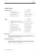
Hardware Outputs
Analog (0 to 10V)
Application
• Cooling valve actuator
2281, 2283, 2287
• Face-bypass damper actuator
2281, 2283, 2284, 2286
• Heating valve actuator
2281, 2283, 2284, 2286, 2287
• Outdoor air damper actuator
2281, 2283, 2284, 2286
Digital
Application
• Auxiliary radiation electric coil contact; or,
auxiliary radiation two-position valve actuator
2281, 2283, 2284, 2286
• Unit fan
2281, 2283, 2284, 2286, 2287
• First stage electric heat
2281, 2283, 2284, 2286
• Second stage electric heat
2281, 2283, 2284, 2286
• Third stage electric heat
2281, 2283, 2284, 2286
• Two-position cooling valve actuator
2281, 2283, 2284, 2286
• Two-position heating valve actuator
2281, 2283, 2284, 2286
• DX coil
2284, 2286, 2287
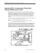
Power Wiring
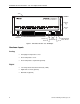
The controller is powered by 24 Vac and connects to the two screw terminals on the
controller. Labeled “C” (Common) and “H” (Hot) on the terminal block labeled “24 VAC”. No
earth-ground connection is required (Figure 2).
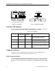
Communication Wiring
The controller connects to the field panel by means of a Floor Level Network (FLN) trunk.
Communication wiring connects to the three screw terminals on the controller labeled “+”
(positive), “-“ (negative), and “S” (Shield) (Figure 3).