
Installation Instructions

Installation Instructions
Document No. 540-566
April 10, 2008
Smoke Control
Listed Heat Pump Controller — Single Stage
24 V-AC
CH
CH
DO 1 DO 2 DO 3 DO 4 DO 5
NO C NO C NO C NO C NO C
DO 6 DI 3 DI 2 FLN
TRUNK
NO C
POWER
TRUNK
TERMINATIONS
FLN TRUNK
TERMINATIONS
MOUNTING
HOLE
(2)
CONTROLLER
BOARD
COVER
MOUNTING
RAIL
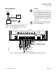
DO LEDS
INPUT/OUTPUT TERMINATIONS
TRANSMIT LED
RECEIVE LED
AI 3
TX RX + - S
+-
S
BST RTS
1 2 3 4 5 6 7 8 9 10 11 12 13 14 15 16
1 2 3 4 5 6 7 8 9 10 11 12 13 14 15 16
TEC0168-SR1
BST LED ROOM TEMPERATURE
SENSOR/MMI PORT
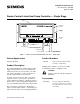
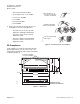
Figure 1. Smoke Control Listed Heat Pump Controller — Single Stage.
Control Applications
2070 thr
ough 2072
Produc
t Description
The Terminal Equipment Controller (TEC) provides
high performance DDC of pressure-independent,
variable-air-volume zone-level routines. The TEC
can operate stand-alone or can be networked to
perform complex HVAC control functions.
The TE
C can also be used as part of a Siemens
engin
eered smoke control system. The TEC are
used t
o initiate the operations of dampers and fans
but th
e smoke control strategy will be initiated from
any of
the APOGEE field panels and not by the TEC.
These instructions explain how to field install or
replace a Heat Pump Controller — Single Stage (for
single and dual compressor heat pump applications).
Product Numbers
540-10
5K
Smoke Control Listed Heat Pump
Controller — Single Stage
Shipping carton includes a controller assembly,
mounting rail, and two self-tapping screws.
CAUTION:
Keep the unit in its static-proof bag until
installation.
Accessories
540-658P25 Low cost temporary temperature
sensor that enables space control if
the permanent room or duct sensor is
not installed.
I
tem Number: 540-566, Rev. BA
P
age 1 of 6