
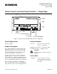
Installation Instructions

Document No. 540-566
Installation Instructions
April 10, 2008
Parts for Smoke Control Compliance
540-155K
Smoke Control Listed Small
Equipment Controller Enclosure
550-002K
Smoke Control Listed Large
Equipment Controller Enclosure
ZBX-XXXX
a
Smoke Control Listed Large
Equipment Controller Enclosure
5041MWCB UL Listed Class 2 transformer
with 120/240/277/480 Vac
50/60 HZ 0.4A primary w/ hub
and 24Vac 50VA secondary w/
hub and circuit breaker
10041MWCB UL Listed Class 2 transformer
with 120/240/277/480 Vac
50/60 HZ 0.5A primary w/ hub
and 24Vac 96VA secondary w/
hub and circuit breaker
KELEAM-2483-OA ULListedClass2Transformer
with primary 120V 60 HZ 0.2A
secondary 24 Vac 30 VA
529-804 Receptacle assembly consisting
of a UL Listed 2x4 junction box
andULListedreceptacle
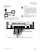
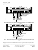
a. Enclosure part number ZB-X-XXXX, where the first
X can be 9 or any letter from A to N represents the
type of TEC module installed/to be installed in the
enclosure, and XXXX can be any 4 alphanumeric
characters represent the TEC HVAC application.
For smoke control application, primary
rating is only 120V/ 60 HZ
Parts for CE Compliance:
550-705
Clamp-on ferrite filter (10 pack).
588-100 series
Approved 2-RJ11 RTS cable in 25’,
50’, or 100’ (7.6 m, 15.2 m, 30.48 m).
Caution Notation
CAUTION:
Equipment damage or lo
ss of data may
occur if you do not fol
low the procedures
as specified.
Expected Installation Times
10 minutes.
Required Tools and Materials
• Electro-Static Discharge (ESD) wrist strap
• Flat-blade screwdriver (1/8-inch blade width).
•Smallflat-blade screwdriver
• Cordless drill/driver set
• 1/4-inch (6.35 mm) hex nut bit
Prerequisites
• Heat pump installed
• 24 Vac Class 2 power source
• Supply power to the unit is OFF
• If required, controller enclosure installed
• Room temperature sensor installed (optional).
(If desired, a low-cost temporary temperature
sensor is available that plugs into the RTS
port of the TEC (P/N 540-658P25), providing
temperature input and actual space control
until the permanent room or duct sensor is
installed.)
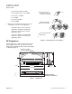
If the controller is being installed on a box
with1ormorestagesofelectricheat,
the 550-809 MOV with pre-terminated
spade connectors must be installed across
the manufacturer-supplied airflow switch.
MOV’s can be installed at the time the
controller is factory mounted; coordinate
with the box manufacturer prior to order
placement. For field installation, reference
document 540-986.
Instructions
All wiring must conform to NEC and local
codes and regulations.
Page 2 of 6 Siemens Building Technologies, Inc.