
Installation Instructions

Document No. 540-566
Installation Instructions
April 10, 2008
• Transformer: primary 14 AWG
• 24 Vac Input Power: 14 to 18 AWG
• DO:AI:18to20AWG
•DI:18AWG
• LAN:20to24AWG
•RST:24AWG
6. Refer to the following documents when used
configuring for smoke control application:
• 125-1806: Smoke Control Systems
Application and Engineering Manual
• 125-1816: Smoke Control System
Application Guide
• 125-1817: NFPA and UL Standards
Relevant to Smoke Control System
Application Guide
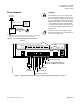
CE Compliance
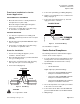
If CE compliance is required, a ferrite filter must be
placed approximately 1–2 cm from the end of the
cable being shielded (RTS cable and the point wiring
for AI3/DI3) (Figure 4).
TEC0320R3
1- 2 cm
1
Place the filter 1-2 cm
from the end of the cable
or wiring to be shielded.
2
Wind the cable tightly
twice around the filter.
3
Close the filter and wrap
with a zip tie.
Figure 4. Ferrite filter(s) for CE Compliance.
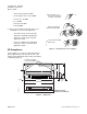
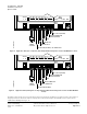
#8 TAPPING SCREW HOLE
11/64 (4) DIA. CLEARANCE
T
EC0169R4
7-5/16 (186)
1-27/32
(47)
3
/16 (5)
C
L
7-11/16 (195)
4-1/8
(105)
DIMENSIONS IN INCHES
MILLIMETERS IN PARENTHESE
S
Figure 5. Dimensions.
Page 4 of 6 Siemens Building Technologies, Inc.