
Installation Instructions
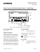

Document No. 540-566
Installation Instructions
April 10, 2008
24 V-AC
TX
RX
FLN
TRUNK
+ - S BST
RTS
DO 1
NO C
DO 2
NO C
DO 3
NO C
DO 4
NO C
DO 5
NO C
DO 6
NO C
DI 3
AI 3
DI 2
1 2 3 4 5 6 7 8 9 10 11 12 13 14 15 16
1 2 3 4 5 6 7 8 9 10 11 12 13 14 15 16
ROOM TEMPERATURE SENSOR
MIXED AIR TEMPERATURE
SENSOR (OPTIONAL)
WALL SWITCH (OPTIONAL)
FAN
COMPRESSOR
REVERSING VALVE
ELECTRIC HEAT (OPTIONAL), OR COMPRESSOR 2
TEC2071WD-SR1
C H
Y1 G
Y2
DAMPER
ACTUATOR
CW
COMMON
CCW
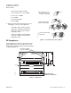
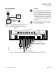
Figure 8. Application 2071 (Two Compressor Heat Pump with Reversing Valve Control and Mixed Air Control).
24 V-AC
TX
RX
FLN
TRUNK
+ - S BST
RTS
DO 1
NO C
DO 2
NO C
DO 3
NO C
DO 4
NO C
DO 5
NO C
DO 6
NO C
DI 3
AI 3
DI 2
1 2 3 4 5 6 7 8 9 10 11 12 13 14 15 16
1 2 3 4 5 6 7 8 9 10 11 12 13 14 15 16
ROOM TEMPERATURE SENSOR
MIXED AIR TEMPERATURE
SENSOR (OPTIONAL)
WALL SWITCH (OPTIONAL)
FAN
COOLING COMPRESSOR
HEATING COMPRESSOR
ELECTRIC HEAT (OPTIONAL)
TEC2072WD-SR1
C H
Y1 G
Y2
DAMPER
ACTUATOR
CW
COMMON
CCW
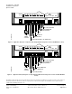
Figure 9. Appl
ication 2072 (Heating and Cooling Heat Pump without Reversing Valve Control and with Mixed Air
Control).
Information in this document is based on specifications believed correct at the time of publication. The right is reserved to make changes as
design improvements are introduced. Product or company names mentioned herein may be the trademarks of their respective owners.
© 2008 Siemens Building Technologies, Inc.
Siemens Building Technologies, Inc. Your feedback is important to us. If you have Document No. 540-566
1000 Deerfield Parkway comments about this document, send them to Country of Origin: US
Buffalo Grove, IL 60089-4513 SBT_technical.editor.us.sbt@siemens.com. Page 6 of 6
U.S.A.