
Installation Instructions

Installation Instructions
Document No. 540-1032
May 3, 2017
Room Pressurization Controller
–
Pneumatic
Output
Item Number: 540-1032, Rev. FA Page 1 of 7
Product Description
These instructions explain how to field install (pages
1 through 3) or replace (pages 3 through 4) a Room
Pressurization Controller – Pneumatic Output with or
without Autozero Modules.
Product Number
540-716 Room Pressurization Controller –
Pneumatic Output
540-717 Room Pressurization Controller –
Pneumatic Output with Autozero
Modules
540-514N Room Pressurization Controller
Board – Pneumatic Output
(replacement)
Shipping carton includes a pre-assembled metal
enclosure with controller board and cover, pneumatic
output modules, Autozero Modules with brackets
(optional), and four self-tapping/drilling screws.
Installation Conventions
CAUTION:
Equipment damage or
loss of data may occur if
you ds not follow
procedures as specified.
Required Tools
• Electro-Static Discharge (ESD) wrist strap
• Small flat-blade screwdriver
• Medium flat-blade screwdriver
• Medium-duty electric drill
• 1/4 in. (6.35 mm) hex nut bit
• Portable Operator’s Terminal with Controller
Interface Software Rev. 2.0 or later (required
for controller replacement only)
Additional tools needed if not using self-tapping
option:
• 1/4 in. (6.35 mm) hex nut driver
• 1/8 in. (3 mm) bit
Prerequisites
• (Optional) Room temperature sensor
installed
• Air velocity sensors installed in ducts
• A source of 24 Vac Class 2 power available
• Supply power to the unit is OFF
• An air supply line is available at the controller
Expected Installation Time
New controller installation 10 minutes
Replacement (old controller has
removable terminal blocks)
6 minutes
Replacement (old controller does
not have removable terminal
blocks)
16 minutes
NOTE: You may require additional time for
database work at the field panel.
New Installation Instructions
NOTE: These steps only refer to new installations.
For replacement instructions, refer to pages 3-4. For
Autozero Module installation, refer to instruction
540-199.
The following tasks can be performed by the
electrician:
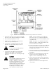
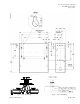
1. Loosen, but do not remove, the cover screws
and remove the enclosure cover. Using the rear
panel of the enclosure as a template (Figures 1
and 2), mark the location for the four screw
holes where you will install the enclosure.
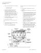
2. Do one of the following:
• If using the self-tapping screws: Using
the drill and the hex nut bit, start the
screws. (Screws do not require starter
holes.)
• If not using the self-tapping screws: Drill
four
1/8 in. (3 mm) pilot holes for the screws.
Using the hex nut driver, start the screws.