
Installation Instructions

Document Number 540-1032
Installation Instructions
May 3, 2017
Page 6 of 7 Siemens Industry, Inc.
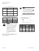
Table 1. Application Descriptions.
Application Description Figure
2215 CAV/VAV Room
Pressurization with
Hot Water Reheat
7
2217 VAV Room
Pressurization with
Hot Water Reheat
7
2219 CAV Room
Pressurization with
Hot Water Reheat
7
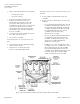
Table 2. Air Velocity Sensor Connections.
Application
Supply AVS
HI and LO
Exhaust AVS
HI and LO
2215 Supply Pickup Exhaust Pickup
2217 Supply Pickup Exhaust Pickup
2219 Supply Pickup Exhaust Pickup
CAUTION:
The Room Pressurization Controller
– Pneumatic Output controls 24 Vac
loads only. The maximum rating is
12 VA for each DO. For higher VA
requirements, 110 or 220 Vac
requirements, separate
transformers used to power the
load, or DC power requirements,
use an interposing 220V 4-relay
module (TEC Relay Module P/N
540-147).
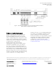
NOTE: Refer to the unit wiring diagrams or consult
with the local representative if terminations are
missing or are different.
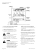
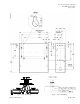
NOTE:
When wiring any actuator that uses a 0
to 10V control signal and ties AC neutral
to DC common, an additional wire must
connect the actuator AC neutral to the
DC common of the PTEC/TEC AO
being used to control the actuator.
Figure 6. 24 Vac Modulating Control.
Actuator
Symbol
TEC
Connection
Function Terminal
Connection
Standard
Color
1 H Supply (SP) G Red
2 C Neutral (SN) G0 Black
8 AO3 – 15
(+)
0 to 10V
input signal
Y Gray
-- C to AO3
16 (-)
Common
jumper
-- --