
Data Sheet for Product
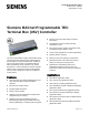
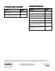
Table Of Contents

Page 2 of 6
Siemens Industry, Inc.
VAV Parallel Fan Powered with Hot Water Reheat
(Application 6527)
Control algorithms are preprogrammed. The controller
is ready to operate after selecting the application. If
desired, the operator may adjust the air volume
setpoints in cfm (lps), room temperature setpoints and
other parameters. The controller is designed for
operation and modification without vendor assistance.
If required, new custom code using our PPCL
programming language can be added to replace or
supplement the standard application residing in the
controller. This provides the flexibility to meet many
job specifications with the assurance of having a
proven and tested standard application to rely upon.
Hardware
Controller Board
The Siemens BACnet PTEC Terminal Box (VAV)
Controller consists of an electronic controller
assembly and on-board differential pressure
transducer(s).
This controller provides all wiring terminations for
system and local communication and power. The
cable from the room sensor (purchased separately)
connects to an RJ-11 jack on the controller. All other
connections are removable terminal blocks. The
controller assembly is mounted on a plastic track that
mounts directly on the terminal box. An optional
enclosure (P/N 550-002) protects the controller
assembly.
Autozero Modules are available for mounting on the
controller for those applications where uninterrupted
airflow is necessary. A Pneumatic Transducer
provides control of pneumatic damper and valve
actuators.
The controller interfaces with the following external
devices:
Averaging air velocity sensors provided by VAV
terminal unit manufacturers
Floating control valve and damper actuators
Temperature sensors (room, duct, immersion, and
outside air)
Service and commissioning tools
Digital input devices (dry contacts from motion
sensors, alarm contacts)
Digital output devices (fan, stages of electric heat)
Room Sensor
The room sensor connection to the controller board
consists of a quick-connect RJ-11 jack. This
streamlines installation and reduces controller start-up
time.
Combination Temperature and Relative
Humidity Models
The Series 2200 range of TEC room units includes
combination temperature and humidity models. For
these models, both temperature and relative humidity
values are passed digitally to the TEC. This
information is passed from the room unit through the
RJ-11 cable to the RTS port on the TEC. See the
Series 2200 Temperature Room Units for TEC and
ATEC Technical Specification Sheet
(149-820), for
more information.
Terminal Box Controller
Specifications
Dimensions 4-1/8" W × 11-1/4" L × 1-1/2" H
Weight approx. 3 lbs (1.35 kg)
Controlled Temperature
Accuracy, Heating or
Cooling
±1.5°F (0.9°C)
Power Requirements
Operating Range 19.2 to 27.6 Vac, 50 or 60 Hz
Power Consumption 10 VA (plus 12 VA per DO)
Inputs
Analog 1 room temperature sensor
1 velocity sensor
1 setpoint (optional)
2 auxiliary temperature sensors
(10K Ω thermistor)
1 selectable 0-10 Vdc/4-20 mA
Digital 2 dry contacts
Outputs
Analog 3 0-10 Vdc
Digital 8 DO 24 Vac optically isolated
solid state switches @ 0.5 amp