
Installation Instructions

Installation Instructions
Document No. 540-1033
October 26, 2016
Room Pressurization Controller –
Electronic Output
Item Number: 540-1033, Rev. DA Page 1 of 6
Product Description
These instructions explain how to field install or
replace a Room Pressurization Controller (RPC) –
Electronic Output with or without Autozero Modules.
Product Number
540-516N Room Pressurization Controller –
Electronic Output
540-517N Room Pressurization Controller –
Electronic Output with Autozero
Modules
Shipping carton includes a controller assembly
(controller board and cover), a mounting rail,
Autozero Modules with brackets (optional), and two
self-tapping/drilling screws.
NOTE: Keep the controller assembly in its static-
proof bag until installation.
Installation Conventions
CAUTION:
Equipment damage or loss
of data may occur if the
user does not follow
procedure as specified.
Required Tools
Electro-Static Discharge (ESD) wrist strap
Small flat-blade screwdriver
Medium flat-blade screwdriver
Medium-duty electric drill
1/4-inch (6.35 mm) hex nut bit
Portable Operator’s Terminal with Controller
Interface Software (CIS) Rev. 2.0 or higher
(controller replacement only)
Additional tools needed if not using self-tapping option:
1/4-inch (6.35 mm) hex nut driver
1/8-inch (3 mm) bit
Prerequisites
Room temperature sensor installed (optional)
Air velocity sensors installed in ducts
24 Vac Class 2 power source
Supply power to the unit is OFF
Autozero Modules with brackets are on hand
(optional)
If required, controller enclosure installed
Expected Installation Time
New controller installation
10 min.
Replacement with removable
terminal blocks
6 min.
Replacement without removable
terminal blocks
16 min.
NOTE: You may require additional time for
database work at the field panel.
New Installation Instructions
NOTE: For Autozero Module installation, refer to
Installation Instructions (540-199).
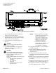
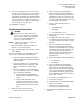
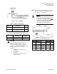
1. Using the mounting rail as a template (See
Figures 1 and 2), mark the location for the two
screw holes where you will install the controller
assembly.
2. Do one of the following:
If using the self-tapping screws: Using
the drill and the hex nut bit, fasten the
mounting rail. (Screws do not require starter
holes.)
If not using the self-tapping screws: Drill
two 1/8-inch (3 mm) pilot holes. Align the
mounting rail with the holes. Using the hex
nut driver, fasten the mounting rail with the
No. 6 or No. 8 screws.