
Installation Instructions

Document No. 550-150
Installation Instructions
July 25, 2014
Siemens Industry, Inc. 3 of 6
NOTE:
If the controller is being installed on
a
box with 1 or more stages of electric
heat, the 550-809 MOV with pre-
terminated spade connectors must
be installed across the manufacturer-
supplied airflow switch. MOVs can
be installed at the time the controller
is factory mounted; coordinate with
the box manufacturer prior to order
placement. For field installation, see
Metal Oxide Varistor Kit Installation
Instructions
(540-986).
NOTE:
A low-cost temporary RTS (540-
658P25) is available that plugs into
the RTS port on the controller,
providing temperature input and
actual space control until a
permanent RTS is installed.
Installation Instructions
NOTE:
All wiring must conform to national
and local codes and regulations
(NEC, CE, etc.).
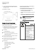
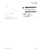
1. Secure the mounting rail in the controller’s
desired location.
2. Place the ESD wrist strap on your wrist and
attach it to a good earth ground.
3. Remove the controller from the static proof bag
and snap it into place on the mounting rail.
4. Connect the FLN.
5. Connect the point wiring (see
Wiring Diagram
s).
6. Plug the room temperature sensor cable into the
RTS port.
7. Connect the power trunk. DO NOT apply power
to the controller without first consulting the
specialist. This TEC is designed to work with 2-
wire AC power (Neutral and Phase (hot) at 24
Vac +/-20%. Use of the earth terminal is optional
and if used it should be connected to the nearest
earth ground (building steel, conduit or duct work
(if earthed)).)
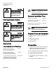
CAUTION
It is very important that the
neutral that supplies the TEC
be earth grounded at the
source of the 24 Vac power.
Possible erratic equipment
operation or damage if
neutral is left floating.