
Installation Instructions

Document No. 550-150
Installation Instructions
July 25, 2014
Page 4 of 6 Siemens Industry, Inc.
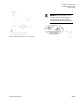
Connect the tubing from the air velocity sensor
pickup to the ports on the controller. Connect HI
to HI and LO to LO.
The installation is complete.
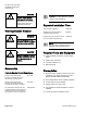
Smoke Control Compliance
The following instructions and information apply if
used for smoke control sequence.
1. Install Smoke Control Listed products, enclosure
and transformer (see
Parts for Smoke Control
Compliance
section for more information).
2. Input Rating:
- 24V 60 HZ 42 VA
3. Digital Output (DO) Electrical Ratings:
- Transformer P/N TR100VA004: 5VA per DO/
maximum 40 VA total.
4. The room temperature sensor (RTS) is installed
in the same room as the TEC.
5. Connection from the TEC to the field panel is a
maximum 4000 feet, 24 AWG minimum.
6. Wiring Range:
- Transformer: primary 14 AWG
- 24 Vac Input Power: 14 to 18 AWG
- DO: AI: 18 to 20 AWG
- DI: 18 AWG
- LAN: 20 to 24 AWG
- RST: 24 AWG
All circuits are power limited; FLN (NETWORK) is
RS-485, RTS (STAT) is RS-232.
See the following documents for more information
on configuring smoke control applications:
Smoke Control Systems Application and
Engineering Manual (
125-1806)
Smoke Control System Application Guide (
125-
1816)
NFPA and UL Standards Relevant to Smoke
Control System Application Guide (
125-1817)
NOTE:
The 24 Vac relay module is not
applicable for smoke control
application.
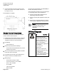
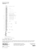
Wiring Diagram
CAUTION
The controller’s DOs control
24 Vac loads only. The
maximum rating is 12 VA for
each DO. An external
interposing relay is required
for any of the following:
• VA requirements higher than
the maximum
• 110 or 220 Vac
requirements
• DC power requirements
• Separate transformers used
to power the load
(for example part number
540-147, Terminal Equipment
Controller Relay Module)