
Installation Instructions

Rev. 2, 2/91 Installation Instruction 544-404
Copyright © 1991 by Landis & Gyr Powers, Inc.
Printed in U.S.A. Page 1 of 1
INSTALLATION INSTRUCTIONS
UC Processor Card
PRODUCT DESCRIPTION
The UC processor card contains the microprocessor,
memory, communication circuitry, and miscellaneous timing
circuitry. It also contains a real-time clock with a lithium
battery for backup.
PRODUCT NUMBER
544-110
REQUIRED TOOLS
None
PREREQUISITES
wrist strap
card cage installed
power suppy installed
INSTRUCTIONS
NOTE: Handle the UC processor card with care. Wear a
wrist strap and try not to touch any of the card’s
components. When installing the card, hold it at
its edges.
Before sliding the UC processor card into the
card cage slot, check that the battery mylar slip
has been removed.
If you are removing an existing processor card, proceed to
Step 1. If you are installing a processor card, skip to Step 4.
1. Turn off the Unitary Controller’s power.
2. Loosen each of the wing nuts on the card cage cover
and remove them. Take off the card cage cover.
3. Use the card extractors to slide the existing processor
card out of its card cage slot.
4. Remove the processor card from the package.
5. Find the battery and remove the mylar slip from the
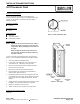
battery holder. Refer to Figure 1.
6. Position the processor card so it’s components face left,
to the inside of the card cage. Gently slide the processor
card into the card cage’s leftmost card guide. Refer to
Figure 2.
7. Gently push the processor card into the connector on the
backplane. The card should snap firmly into place.
8. Replace or install the card cage cover.
9. Tighten the wing nuts to secure the card cage cover.
EXPECTED INSTALLATION TIME
5 Minutes
Figure 1. Battery with Mylar Slip.
Figure 2. Card Cage.