
Installation Instructions
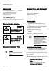
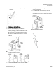
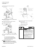
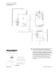
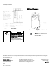
Table Of Contents

Document No. 540-1035
Installation Instructions
June 10, 2015
Page 2 of 6 Siemens Industry, Inc.
Accessories
Low cost temporary temperature
sensor, 10K Ω thermistor with RJ11 (1”
long), that enables space control if the
permanent room or duct sensor is not
installed (pack of 25).
540-658P25
Parts for CE Compliance:
RJ11 (6 wire) RTS cable in 25 ft, 50 ft, or
100 ft (7.6 m, 15.2 m, 30.48 m).
588-100 series
Warning/Caution Notation
WARNING
Personal injury/loss of life may
occur if you do not follow the
procedures as specified.
CAUTION
Equipment damage or loss of
data may occur if you do not
follow the procedures as
specified.
Expected Installation Time
25 minutes
NOTE:
You may require additional time
for database work at the field
panel.
Required Tools and Equipment
4 mm hex wrench
Small flat-blade screwdriver
1/4-inch hex drill/driver set
Marker or pencil
Torque wrench
ESD wrist strap
Prerequisites
Wiring conforms to NEC and local codes and
regulations. For further information see the
Wiring Guidelines Manual
(125-3002).
(Optional)
Room temperature sensor installed.
24 Vac Class 2 power available.
Supply power to the unit is OFF.
Any application specific hardware or devices
installed.
Air velocity sensors installed in ducts.
NOTE:
A low-cost temporary RTS
(540-658P25) is available that
plugs into the RTS port on the
controller, providing
temperature input and actual
space control until a permanent
RTS is installed.
Installation Instructions
Use earth ground isolating step-down Class 2
transformers. Do not use autotransformers.
Determine the supply transformer rating by summing
total VA (3.5 VA per unit) of all actuators used. It is
recommended that one transformer power no more
than 10 actuators.
1. Determine the size of the damper shaft by doing
one of the following:
- If the damper shaft is 1/2-inch, proceed to
Step 2.
NOTE: The actuator comes with a factory
installed 1/2-inch damper shaft guide.
- If the damper shaft is 5/8-inch,