
Installation Instructions
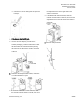
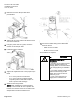
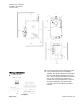
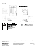
Table Of Contents

Document No. 540-1035
Installation Instructions
June 10, 2015
Page 4 of 6 Siemens Industry, Inc.
4. Mark the end of the damper shaft with a
pencil/marker.
5. Tighten the set screw until the first thread can be
seen in the shaft hole.
6. Using the pencil mark as a guide, mount the
actuator on the damper shaft.
7. Install the position indicator.
8. Tighten the adjustment lever to the proper torque
listed:
- 70 +/- 5 inch-pounds for solid metal.
- 37 +/- 2 inch-pounds for plastic graphite
composite (hollow metal shafts require an
insert to prevent shaft damage).
9. Attach the mounting bracket.
NOTE: When installing the mounting bracket
directly on the ductwork be sure to position the
bracket such that the screws do not obstruct the
damper blade movement inside the box.
10. Connect the airflow tubing for the Differential
Pressure Sensor.
- RED connects to HIGH.
- BLUE connects to LOW.
The installation is complete.
WARNING
Installations requiring CE
Compliance
— All wiring for CE rated actuators
must be Separated Extra Low
Voltage (SELV) or Protective Extra
Low Voltage (PELV) per HD384-4-
41.
— Use safety-isolating transformers
(Class III transformer) per EN
61558. They must be rated for
100% duty cycle.
— Over current protection for
supply lines is maximum 4A.