
Installation Instructions

Installation Instructions
Document No. 129-539
November 5, 2008
TEC Digital Flush Mount Sensor Wall
Mounting Kit
Item Number 129-539, Rev. AA Page 1 of 2
Product Description
This kit allows users to mount the TEC Semi-Flush
Mount Room Temperature Sensor on standard drywall
or to a 2" × 4" electrical box. It can also be used on
plywood, paneling, or other types of wall sheathing
material.
Contents
• Backplate (1)
• 6-32 × 1-7/8" Screw (2)
• #6-8 × 3/4" Plastic wall anchor (2)
Product Number
AQA1200
Required Tools
• Pencil or marker
• Small level
• 3/16” drill bit
• Med. duty electric or battery operated hand drill
• Phillips head screw driver
• Drywall saw
• Linesman pliers
Expected Installation Time
15 minutes
Prerequisites
• Review these instructions before beginning.
• Installed: Appropriate field wiring (standard six-
conductor room sensor cables, plenum or non-
plenum as required), within the maximum
wiring run length for the individual equipment
controller. The maximum recommended length
is 100 feet (30 m).
• All wring must comply with the National Electric
Code (NEC) and local regulations.
Locate the sensor:
• According to design specifications and local
regulations.
• Where the air circulates around it freely (not in
recessed areas or behind doors).
• Away from drafts caused by doors, windows,
outside walls, air registers, pipes, and return air
plenums, and so on.
• On an inside wall (preferably), about 5 feet
(1.5 m) above the finished floor.
Installation
A typical installation procedure consists of the following
steps:
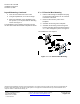
Drywall Mounting
1. Place the backplate in the up position "↑" level
on the wall and trace inside to make roughly a
2-1/16" × 3-1/2" rectangle. See Figure 1.
Figure 1. Drywall Mounting.
2. Choose two holes and mark their centers.
3. Drill two 3/16" holes where the hole centers are
marked.