TEC Controller Constant Volume with Electric Reheat, Application 2032 Application Note 140-1022 2015-08-07 Building Technologies
Table of Contents Overview ............................................................................................................................. 4 Hardware Inputs .................................................................................................................. 5 Hardware Outputs ................................................................................................................ 5 Secure Mode Operation.......................................................................
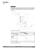
Overview Hardware Inputs Overview In Application 2032, the controller provides a constant volume of air to the room during occupied periods, and a lower constant volume of air to the room during unoccupied periods. Reheat is provided by three stages of electric heat. In order for the application to work properly, the central air handling unit must provide pre-conditioned air to the terminal box. Application 2032 Control Drawing. Application 2032 Control Schedule. 4 Siemens Industry, Inc.
Overview Hardware Inputs Hardware Inputs Analog Air velocity sensor Room temperature sensor (Optional) Room temperature setpoint dial (Optional) Auxiliary temperature sensor (100K thermistor) Digital (Optional) Night mode override (Optional) Wall switch Hardware Outputs Analog None Digital (Optional) Autozero Module Damper actuator Stage 1 electric reheat or, 2-position heating valve (Optional) Stage 2 electric reheat (Optional) Stage 3 electric reheat Secure Mode Operation
Sequence of Operation Control Temperature Setpoints Sequence of Operation The following paragraphs present the sequence of operation for Application 2032 -Electric Reheat. Control Temperature Setpoints Depending on the controller’s current operational mode (occupied or unoccupied), CTL STPT holds the value of one of the following setpoints. NOTE: This application does not automatically switch between heating and cooling.
Sequence of Operation Control Temperature Setpoints The setpoint deadband exists to allow the controller to provide a separation of the heating and cooling temperature setpoints when a setpoint dial is enabled. The setpoint deadband is the difference between the cooling and heating day setpoints (DAY CLG STPT - DAY HTG STPT). The setpoint deadband can be disabled by setting DAY HTG STPT equal to DAY CLG STPT. When DAY HTG STPT does not equal DAY CLG STPT, a setpoint deadband (or zero energy band) is used.
Sequence of Operation Room Temperature and CTL TEMP CTL STPT Using Standard/Absolute Mode (Digital Room Unit, Revision 26 and later) Digital Room Unit (2200/2300 Series Firmware Revision 26 and later) When STPT SPAN is set to 0, the room setpoint adjustment on the digital room unit functions in a standard mode. The range of the adjustment is based on RM STPT MIN and RM STPT MAX. CTL STPT is set equal to RM STPT DIAL.
Sequence of Operation Control Loops Control Loops Flow Loop – maintains the point FLOW STPT by modulating the supply air damper point, DMPR COMD. The flow loop maintains the airflow at either OCC FLOW or UNOCC FLOW depending on the value of OCC.UNOCC. To enhance stable flow control, an advanced algorithm is used to calculate a controllable setpoint as the value approaches zero cfm (lps). FLOW is the input value for the flow loop.
Sequence of Operation Electric Heat Interlock Electric Heat Interlock Terminal unit heat stages The electric heat stages will be enabled as long as FLOW > EHEAT FLOW. The electric heat stages will not be disabled (turned OFF) until FLOW < EHEAT FLOW 5%. Once disabled, FLOW must become greater than EHEAT FLOW before the electric heat stages will return to normal control. CAUTION Do not set EHEAT FLOW to less than 5%; otherwise, the electric heat interlock will be disabled.
Sequence of Operation Application Notes Application Notes If FLOW is oscillating while FLOW STPT is constant, then the flow loop requires tuning. The controller, as shipped from the factory, keeps all associated equipment OFF. Spare DOs can be used as auxiliary points that are controlled by the field panel after being defined in the field panel’s database. The combination of DO 3 and DO 4 may be used as auxiliary motor points.
Sequence of Operation Wiring Diagrams Wiring Diagrams NOTE: The controller’s DOs control 24 Vac loads only. The maximum rating is 12 VA for each DO. An external interposing relay is required for any of the following: • VA requirements higher than the maximum • 110 or 220 Vac requirements • DC power requirements • Separate transformers used to power the load (for example, part number 540-147, Terminal Equipment Controller Relay Module) Application 2032 – Constant Volume with Electric Reheat.
Application 2032 Point Database Application 2032 Point Database Point Number Descriptor Factory Default (SI Units) Eng Units (SI Units) Slope (SI Units) Intercept (SI Units) On Text Off Text 1 CTLR ADDRESS 99 -- 1 0 -- -- 2 APPLICATION 2092 -- 1 0 -- -- {04} ROOM TEMP 74.0 (23.44888) DEG F (DEG C) 0.25 (0.14) 48.0(8.88888) -- -- {05} HEAT.COOL COOL -- -- -- HEAT COOL 6 OCC CLG STPT 70.0 (21.20888) DEG F (DEG C) 0.25 (0.14) 48.0(8.
Application 2032 Point Database Point Number Descriptor Factory Default (SI Units) Eng Units (SI Units) Slope (SI Units) Intercept (SI Units) On Text Off Text {41} DO 1 OFF -- -- -- ON OFF {42} DO 2 OFF -- -- -- ON OFF {43} HEAT STAGE 1 OFF -- -- -- ON OFF {44} HEAT STAGE 2 OFF -- -- -- ON OFF {45} HEAT STAGE 3 OFF -- -- -- ON OFF {46} DO 6 OFF -- -- -- ON OFF {48} DMPR COMD 0 PCT 0.4 0 -- -- {49} DMPR POS 0 PCT 0.
Application 2032 Point Database Point Number Descriptor Factory Default (SI Units) Eng Units (SI Units) Slope (SI Units) Intercept (SI Units) On Text Off Text 89 STAGE TIME 10 MIN 1 0 -- -- {91} TOTAL VOLUME 0 (0) CF (L) 4 (113) 0 -- -- {92} CTL STPT 74.0 (23.44888) DEG F (DEG C) 0.25 (0.14) 48.0(8.88888) -- -- {93} FLOW STPT 0 PCT 0.
Issued by Siemens Industry, Inc. Building Technologies Division 1000 Deerfield Pkwy Buffalo Grove IL 60089 Tel. +1 847-215-1000 Document ID 140-1022 Edition 2015-08-07 © Siemens Industry, Inc., 2015 Technical specifications and availability subject to change without notice.