
Installation Instructions

Installation Instructions
Document No. 545-403
February 7, 2003
Controller Module Memory Upgrade
Information in this publication is based on current specifications. The company reserves the right to make changes in specifications and
models as design improvements are introduced. Other product or company names mentioned herein may be the trademarks of their
respective owners. © 2002 Siemens Building Technologies, Inc.
Siemens Building Technologies, Inc.
1000 Deerfield Parkway
Buffalo Grove, IL 60089-4513
U.S.A.
Your feedback is important to us. If you have
comments about this document, please send
them to technical.editor@siemens.com
Document No. 545-403
Printed in the U.S.A.
Page 1 of 1
Item Number: 545-403-04, Rev. 010
Product Description
The 512K-memory board upgrades the MBC/RBC
Controller Module Random Access Memory (RAM)
from 256K bytes to 512K bytes.
Product Numbers
545-702 512K Memory Upgrade
Required Tools
• Electro-static discharge wrist strap
Expected Installation Time
35 minutes
Caution Notation
CAUTION:
Equipment damage or loss of
data may occur if you do not
follow the procedures as
specified.
Prerequisites
CAUTION:
Be sure to backup your database. Data is lost
when the power is turned OFF and the memory
board is removed from the Controller Module.
Installation
1. Switch the field panel power OFF.
2. Place the electro-static discharge wrist strap
around your wrist and secure the clip to a good
earth ground. Refrain from touching any of the
components on the memory board.
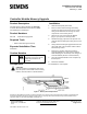
3. Lift the front cover of the Controller Module
(Figure 1) to expose the memory board.
4. Simultaneously pry open both card ejectors and
carefully slide the 256K-byte memory board out of
its slot.
5. Gently slide the 512K-byte upgrade board into the
open guide rails of the controller module until the
board is firmly seated.
6. Remove the old paper label from inside the
Controller Module cover and replace it with the
label identifying the new memory size and type of
Controller Module (Protocol 2 or Stand-alone).
7. Close the Controller Module cover and power up
the field panel.
8. Reload the database.
The installation is now complete.
Figure 1. Memory Board Replacement.