
Installation Instructions

Document No. 550-810
Installation Instructions
November, 2003
Page 2 of 4 Siemens Building Technologies, Inc.
Instructions
WARNING:
Do not open the actuator.
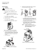
1. Determine the size of the damper shaft.
• If the damper shaft is 1/2-inch, proceed to
Step 2.
NOTE: The ATEC actuator comes with a
factory installed 1/2-inch damper shaft
guide.
• If the damper shaft is 5/8-inch:
a. Remove the 1/2-inch shaft guide, Figure 3.
b. Proceed to Step 2.
• If the damper shaft is 3/8 inch:
a. Remove the 1/2-inch shaft guide, Figure 3.
TEC0411R1
Figure 3. Removing the 1/2-inch shaft guide.
b. Use the 3/8-inch adapter, provided in the
actuator packaging, Figure 4. Hold the shaft
insert so that the raised tabs are inserted last
when placing the insert into the back of the
actuator.
c. Proceed to Step 2.
TEC0437R1
4
5
90
90
Mounting
3/8-inch
8...10 mm shafts
~
~
Figure 4. Installing the 3/8-inch shaft adapter.
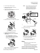
2. Determine the damper blade rotation, clockwise
or counterclockwise to open, Figure 5.
90
90
4
5
"0"
90
90
4
5
CLOCKWISE
TO OPEN
COUNTER
CLOCKWISE
TO OPEN
TEC0438R1
Figure 5. Damper Rotation.
• If the blades will rotate counterclockwise, slide
the manual override switch to manual, and
move the adjustment lever to the right. Return
the switch to automatic, Figure 6.
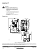
• If the blades will rotate clockwise, slide the
manual override switch to manual, and move
the adjustment lever to the left. Return the
switch to automatic, Figure 6.
NOTE: Changes to MTR SETUP (in the
application) may be necessary during
start-up/commissioning if dampers
open counterclockwise.
45
90
90
TEC0439R1
MANUAL
ADJUSTMENT
LEVER
AUTO
Figure 6. Setting the Direction of Rotation.