
Installation Instructions

Document No. 550-810
Installation Instructions
November, 2003
Siemens Building Technologies, Inc. Page 3 of 4
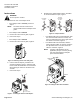
3. Close the damper blades, Figure 8.
4. Mark the end of the damper shaft with a
pencil/marker, Figure 8.
5. Tighten the set screw until the first thread can be
seen in the shaft hole, Figure 7.
TEC0450R1
90
90
4
5
Figure 7. Set screw in shaft hole.
6. Mount the actuator on the damper shaft, Figure 8.
4
5
9
0
90
TEC0440R1
Figure 8. Mounting the actuator.
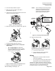
7. Install the position indicator, Figure 9.
8. Tighten the adjustment lever to the proper
torque listed:
• 70 +/- 5 inch-pounds for solid metal
• 37 +/- 2 inch-pounds for plastic graphite
composite (hollow metal shafts require an
insert to prevent shaft damage).
45
90
90
TEC0441R1
4 mm
Figure 9. Position indicator and adjustment lever.
9. Attach the mounting bracket, Figure 10.
NOTE: When installing the mounting bracket
directly on the ductwork be sure to
position the bracket such that the
screws do not obstruct the damper
blade movement inside the box.
TEC0442R1
1/2
1/2
CENTER THE
MOUNTING BRACKET
IN THE SLOT
CAUTION:
These holes for use
with accessory kits only.
Do not use in the
installation of direct-
coupled applications.
1/4 in.
Hex Drive
90
90
4
5
Figure 10. Installing the mounting bracket.
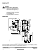
10. Adjust mechanical range.
45
9
0
9
0
TEC0417R1
4 mm
45
90
90
TEC0418R1
<
90
Figure 11. Moving the Mechanical Range Stop.
a. Loosen the stop set screw.
b. Move it along the track to the desired
position, and fasten it in place.
Wiring
• All wiring must conform to NEC and local
codes and regulations.
• Use earth ground isolating step-down Class 2
transformers. Do not use autotransformers.
Determine the supply transformer rating by summing
total VA (4 VA with no load and 28 VA with full load) of
all actuators used. It is recommended that one
transformer power no more than 10 actuators.