TEC Controller Constant Volume - Electronic Output Owner's Manual 125-5070 2015-05-07 Building Technologies
Table of Contents How To Use This Manual .................................................................................................. 4 Chapter 1 – Product Overview ......................................................................................... 6 Hardware Inputs .................................................................................................................. 6 Hardware Outputs ...................................................................................................
How To Use This Manual How To Use This Manual This manual is written for the owner and user of the TEC Constant Volume Controller. It is designed to help you become familiar with the Siemens TEC and its applications. This section covers manual organization, manual conventions, symbols used in the manual, and other information that will help you use this manual.
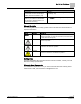
How To Use This Manual Convention Examples Cross references to other information are For more information on creating flowcharts, see indicated with an arrow and the page Flowcharts [→92]. number, enclosed in brackets: [→92] Placeholders indicate text that can vary based on your selection. Placeholders are specified by italicized letters, and enclosed with brackets [ ]. Type A C D H [username] [field panel #].
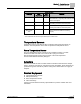
Chapter 1 – Product Overview Hardware Inputs Chapter 1 – Product Overview The TEC Constant Volume Controller is the Siemens Industry FLN controller used in pressure independent Constant Volume applications. It provides Direct Digital Control (DDC) for a number of applications. The controller can operate as an independent, stand-alone, DDC room controller or it can be networked with a field panel. The controller provides all termination, input/output, system and local communication connections.
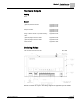
Chapter 1 – Product Overview Hardware Outputs Hardware Outputs Analog None Digital (Optional) Autozero Module Application 2030 Application 2032 Application 2033 Damper actuator Application 2030 Application 2032 Application 2033 Stage 1 electric reheat or 2-position heating valve Application 2032 (Optional) Stage 2 electric reheat Application 2032 (Optional) Stage 3 electric reheat Application 2032 Valve actuator Application 2033 Ordering Notes TEC Constant Volume Controller 540-103N Generic
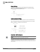
Chapter 1 – Product Overview Power Wiring Power Wiring The controller is powered by 24 Vac. Power wiring connects to the three screw terminals on the controller board labeled “C” (Common), “H” (Hot), and “E” (Earth Ground) on the terminal block labeled “24 Vac”. Communication Wiring The controller connects to the field panel by means of a Floor Level Network (FLN) trunk.
Chapter 1 – Product Overview Temperature Sensors Controller LEDs. LED Type Label (if present)* LED Number Indication DO LED 1 - LED 6 1–6 Indicates the ON/OFF status of the DO associated with it. A glowing LED indicates that the DO is energized. Transmit TX 7 Indicates, when flashing, that the controller is transmitting information to the field panel. Receive RX 8 Indicates, when flashing, that the controller is receiving information from the field panel.
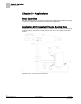
Chapter 2 – Applications Basic Operation Chapter 2 – Applications Basic Operation The TEC Constant Volume Controller provides Direct Digital Control (DDC) technology for pressure independent Constant Air Volume (CAV) applications. Application 2030 Constant Volume Cooling Only In Application 2030, the controller provides a constant volume of air to the room during occupied periods, and a lower constant volume of air to the room during unoccupied periods. Application 2030 - Cooling Only Control Diagram.
Chapter 2 – Applications Application 2032 Constant Volume with Electric Reheat Application 2032 Constant Volume with Electric Reheat In Application 2032, the controller provides a constant volume of air to the room during occupied periods, and a lower constant volume of air to the room during unoccupied periods. Reheat is provided by three stages of electric heat. In order for the application to work properly, the central air handling unit must provide pre-conditioned air to the terminal box.
Chapter 2 – Applications Application 2033 Constant Volume with Hot Water Reheat Application 2033 Constant Volume with Hot Water Reheat In Application 2033, the controller provides a constant volume of air to the room during occupied periods, and a lower constant volume of air to the room during unoccupied periods. Reheat is provided by modulating a hot water valve. In order for the application to work properly, the central air handling unit must provide pre-conditioned air to the terminal box.
Chapter 3 – Point Database Chapter 3 – Point Database Chapter 3 presents a description of the TEC Constant Volume Controller point database, including point descriptors, point addresses, and a listing of applications in which each point is found. Descriptor Address1 Application CTLR ADDRESS 01 All Identifies the controller on the LAN trunk. APPLICATION 02 All Identification number of the program running in the controller. ROOM TEMP {04}2 All Actual reading from the room temperature sensor.
Chapter 3 – Point Database Descriptor Address1 Application Description one is connected. Valid input: YES or NO. DI OVRD SW {19} All Actual indication of the status of the override switch (not physically available on all temperature sensor models) at the room temperature sensor. ON indicates that the switch is being pressed. OFF indicates that the switch is released. Valid input: ON or OFF.
Chapter 3 – Point Database Descriptor Address1 Application Description DO 4 {44} All except 2092 Digital output 4 controls a 24 Vac load with an ON or OFF status. If Motor 2 is enabled, then DO 4 is coupled with DO 3 to control an actuator. HEAT STAGE 2 {44} 2032 This point is DO 4 in applications with electric reheat. This output controls the contactor for the second heating stage and has a status of ON or OFF.
Chapter 3 – Point Database Descriptor Address1 Application Description velocity sensor is located. This value is calculated by the portable operator’s terminal or by the field panel depending on duct shape and size. It is used in calculating all points in units of CFM, CF, LPS, and L. HTG P GAIN 67 2032, 2033 The proportional gain value for the heating temperature control loop. HTG I GAIN 68 2032, 2033 The integral gain value for the heating temperature control loop.
Chapter 3 – Point Database Descriptor Address1 Application Description STAGE COUNT 88 2032 The number of electric heating stages used by the application. DOs associated with unused stages may be used as spare DOs. STAGE TIME 89 2032 The cycle time in minutes for the electric reheat stages.
Chapter 4 – Basic Service and Maintenance Basic Service Information Chapter 4 – Basic Service and Maintenance This chapter describes basic service and maintenance measures you can take when using a TEC. You may want to contact your local Siemens Industry representative if a problem occurs or you have any questions about the controller. NOTE: When troubleshooting, record the problem and what actions were performed immediately before the problem occurred.
Chapter 4 – Basic Service and Maintenance Safety Features Safety Features The controller board stores the controller's address, applications, and point values. In the event of a power failure or a reset, these values are retrieved from the controller's permanent memory and are used by the controller unless overridden by a field panel. If one of the following conditions occurs, the controller will activate safety features present in its fail-safe mode. Sensor failure. Loss of power.
Glossary Glossary This glossary contains the collected terms and acronyms that are used in Siemens BACnet PTEC and TEC Controllers. For definitions of point database descriptors, see Chapter 3 - Point Database, in this manual. airflow Rate at which a volume of air moves through a duct. Usually expressed in cubic feet per minute (cfm) or liters per second (lps). algorithm Mathematical formula and control logic that uses varying inputs to calculate an output value. AVS Air Velocity Sensor.
Glossary Demand Control Ventilation A control algorithm that provides for the control or reduction of outdoor air intake below design rates when the actual occupancy of spaces served by the system is at less than design occupancy. DCV Demand Control Ventilation. DDC Direct Digital Control. Direct digital control The automated control of a condition or process by a digital device (computer). DO Digital Output. Physical output point that sends a two-state signal (ON/OFF, OPEN/CLOSED, YES/NO).
Glossary HMI Human Machine Interface. Terminal and its interface program that allows you to communicate with a field panel or equipment controller. Occupancy sensor A control device that detects presence of people in a space by using infrared or ultrasonic technology. Occupancy sensors are used to save energy by controlling lighting and temperature and, along with CO2 sensors, to provide control input of demand control ventilation (DCV) algorithms.
Glossary UI Universal Input. Can be used as an AI or DI. An AI input is a point receiving a signal that represents a condition that has more than two states. A DI input is a physical input point that receives a two-state signal. unbundle Term used to describe the entering of a point that resides in a controller's database into the field panel's database so that it can be monitored and controlled from the field panel. VAV Variable air volume.
Index Index H A hardware actuators, 9 LEDs, 9 temperature sensors, 9 actuators, 9 damper actuator, 9 valve actuator, 9 algorithm, 20 application, slave mode overview, 12 L LED, 8 Light Emitting Diodes (LEDs), 8 BST, 8 RX and TX, 8 loopout, 21 B basic operation, 10 Basic Sanity Test (BST), 8 basic service information, 18 BST LED, 8 M C mounting bracket, 6 centralized control, 20 Chilled Beam, 20 CO2, 20 control loop, 20 controller LEDs/LED indicators, 8 Terminal Box (VAV) Controller, 6 Terminal E
Index temperature sensors duct temperature sensor, 9 room temperature sensor, 9 RTS, 9 Terminal Box (VAV) Controller product overview, 6 troubleshooting basic service information, 18 TX LED, 8 U unbundle, 23 units, English, 21 25 Siemens Industry, Inc.
Issued by Siemens Industry, Inc. Building Technologies Division 1000 Deerfield Pkwy Buffalo Grove IL 60089 Tel. +1 847-215-1000 Document ID 125-5070 Edition 2015-05-07 © Siemens Industry, Inc., 2015 Technical specifications and availability subject to change without notice.