
Operating Instructions
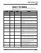
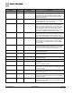
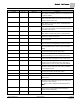
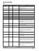
Table Of Contents

Chapter 3 – Point Database
14
Siemens Industry, Inc. Owner's Manual 125-5070
2015-05-07
Descriptor
Address
1
Application
Description
one is connected. Valid input: YES or NO.
DI OVRD SW {19} All Actual indication of the status of the override switch (not
physically available on all temperature sensor models) at the
room temperature sensor. ON indicates that the switch is
being pressed. OFF indicates that the switch is released.
Valid input: ON or OFF.
OVRD TIME 20 All
except
2092 The amount of time, in hours, that the controller will operate
in day/occupied mode when the override switch is pressed
while the controller is in unoccupied mode.
UNOCC OVRD {21} All
except
2092 Indicates the mode that the controller is operating in with
respect to the override switch. UNOCC indicates that the
switch has not been pressed and the override timer is not
active. OCC indicates that the switch has been pressed and
the override timer is active. The controller then uses an
occupied mode temperature set point. This point is only in
effect when OCC.UNOCC indicates UNOCC mode.
DI 2 {24} All Actual status of a contact connected to the controller at DI 2
(screw terminals 15 and 16). ON indicates that the contact is
closed; OFF indicates that the contact is open. If a wall
switch is used, it is connected to DI 2. See
LIGHT SWITCH
.
DI 3 {25} All Actual status of a contact connected to the controller at DI
3/AI 3 (screw terminals 13 and 14). ON indicates that the
contact is closed; OFF indicates that the contact is open.
When a contact is connected at DI 3, AI 3 is not available.
See
AUX TEMP
.
OCC.UNOCC {29} All Indicates the mode in which the controller is operating.
Occupied temperature setpoints will be used in OCC mode.
Unoccupied temperature setpoints will be used in UNOCC
mode. This point is normally set by the field panel.
UNOCC FLOW {31} All
except
2092 The amount of air in CFM (LPS) to be supplied to the space
during unoccupied periods.
OCC FLOW {32} All
except
2092 The amount of air in CFM (LPS) to be supplied to the space
during occupied periods.
AIR VOLUME {35} All Actual amount of air in CFM (LPS) currently passing through
the air velocity sensor.
FLOW COEFF 36 All Calibration factor for airflow.
FAIL MODE 40 All
except
2092 Indicates the desired position of the dampers if the air flow
sensor(s) fail.
Valid input: CLOSED or OPEN.
DO 1 {41} All Digital output 1 controls a 24 Vac load with an ON or OFF
status. If Motor 1 is enabled, then DO 1 is coupled with DO 2
to control an actuator.
DO 2 {42} All Digital output 2 controls a 24 Vac load with an ON or OFF
status. If Motor 1 is enabled, then DO 2 is coupled with DO 1
to control an actuator.
DO 3 {43} All
except
2092 Digital output 3 controls a 24 Vac load with an ON or OFF
status. If Motor 2 is enabled, then DO 3 is coupled with DO 4
to control an actuator.
HEAT STAGE 1 {43} 2032 This point is DO 3 in applications with electric reheat. This
output controls the contactor for the first heating stage and
has a status of ON or OFF.